Search This Blog

Engine faltering under acceleration

22nd Nov 2011.

I fitted the electrics to the rear of the buggy using the coiled wire protectors I had purchased . This gave greater protection to the wiring . With the engine rebuilt I still been having problems with acceleration that had been dogging my new engine for some time . I had tried replacing engine parts to solve this but to date had had little success. The problem was still alluding me and several friends could not resolve this problem either. It had been a busy month with other activities so I was unable to spend as much time as I wanted to.

I replaced the fuel pump with a new fuel pump regulator and pressure gauge in an attempt to see if there was a fueling issue that was preventing fuel reaching the twin carburetors. The fuel pressure was correct and providing 2.5-3 psi on the gauge. I pressure tested the heads and they all came out the same over 980 lbs on each cylinder suggesting I had good compression.

I tried swapping the distributor to see if my 009 distributor was failing this did not improve the situation.

I know I am running 32 Venturi in my DRLA carburetors and am now wondering whether my poor running is because of this ? I rang VW Heratige who told me that the 32 Venturi where better suited to a larger engine they suggested running 30's. I would have to see if I could locate some replacement Venturi/ Chokes to see if this was the fault.

** Photo of Dellorto DRLA 40 Venturi/ Choke provided by courtesy of www.Dellorto.com

Upgrading replacement heads with Heavy Duty Valve Springs

11th Sep 2011.

It had been some time since my problems with my valve springs as I had found it quite difficult to locate some good second hand 1600 heads. Amazingly I found these eventually on hht://www.volkszone.co.uk web site and they where only a few miles away from me the whole time. I was lucky that the heads that I found had come from an engine that had only done 1500 miles or less so the heads had effectively already been run in.

I had managed to find some Heavy duty springs for same on eBay and new that they would have to be fitted to the new heads. This was as I had found to my cost that the standard springs would not take the compression from the ham and high lift rockers. I had also decided that rather than find chromoly push rods at this time I would use a set of bolt together 1:2 rockers I had purchased already.

The first thing I did with the heads was to remove the springs and valves and clean the ports on the heads. This in simple terms means smoothing the inlets to the ports with sand paper or an electric tool.

Fitting the Heavy duty Springs turned out to be a challenge my converted spring removal tool bent under the strain. I knew I would have to buy the bigger valve tool that I had tried to buy the last time from Cool Air before Bug Jam but decided this time to buy it from VW Heritage it arrived a day later.

The tool came in two package a package containing a split pin and the other containing the tool in separate bits. Amazingly there was no instructions for assembly but fortunately I had seen a diagram that I loaded up onto my site before showing it put together. The tool is a fantastic piece of kit but you need to learn how to use it. Firstly there are small pieces of tubing welded to the base these have to be aligned on the valve head . You cannot simply place the head on the tool and do all the valves without moving the head. Secondly when you press down on the arm after locating the tool head on the valve as in the picture the spring gives a little before it hits this block on the base. You need to press the arm quite hard after this to break the seal between the collet's and the retainers, they will usually let go with a thud and the spring will compress allowing the collet's to be picked out of the retainers with a bradel. Once the collet's are removed the arm can be released to allow the spring to be removed. The head then needs to be adjusted before this procedure can be repeated. The new collet's and retains are also heavy duty and it is easy to tell the difference. I found it a fiddle to get the Heavy Duty Valve springs on the tool and head. The main reason for this was the springs seem to be longer as well as thicker. I found that balancing the spring and retainer on the head and pulling down the tool head so it touched i could then push the spring and retainer into the tool head. I also found it difficult to get the collet's in place i found that insert in one then releasing the arm centralized the retainer and made it easier to fit the second collet in. The bradel was extremely useful to move these small collet's about as it had a sharp point.


Once I had fitted the Heavy Duty Springs I fitted the heads to my engine block. The heads push onto the barrels and are bolted up to 35 lbs/ft or 3.2 mKgs depending on your torque ratchet. The Heavy Duty Valves are easily identified as the retainers are a different shape. Once I had the heads torqued up I realized I had forgotten to install the air deflectors under the barrels , these are very important and slot under the barrels. They cannot be fitted with the heads on so I had to remove the heads and refit them a good lesson learned her check they are fitted first. I then fitted my 1:2 bolt up rocker arms you can see they are very similar to the Scat Pro Rockers but do not have quite so much lift. I torqued these up to 18 lbs/ft ( torque settings) I had broken a stud in the past and new these must not be over tightened. I fitted the tine ware over the heads and refitted the fan housing and the Alternator. these are fairly simple jobs apart form ensuring your fan is running freely there is not much more to it than bolting the tin ware together and using the alternator strap to tighten up the alternator. I moved my strap bolt round to the side so it did not foul the linkage kit . I fitted the carburetors and linkage kit with new gaskets (most important). I then left the engine over night so that it could cool enough for the valves to be adjusted. I used my own procedure to adjust the valves.

I just had the electrics to reconnect and decided that it was in need of a little restorations. I had used some spiral wrap before and decided that I would use this to protect the loom . I would have to purchase this and would refit the electrics next time.

Removing and refitting Barrels & Pistons from a twinport beetle engine.

11th August 2011.

It is a very say day today that we remember 10 years ago the atrocity that happened and only hope it makes us stronger.

My previous exploration of my engine had left me finding oil in my barrels and I was lucky to be able to buy some 1641 B&P to fit in place of my 1600 b&P . I had also realized that I had Scatt pro street 1:25 rockers bolted to my heads in addition to the Engle cam.


Removal
Removal of the Barrels and Pistons is fairly straight forward but you need a pair of long nose pliers and a rubber mallet and a socket set drive. I start by removing both cylinders on one side. Making sure to note which cylinder was which by placing them in different areas. With the cylinders carefully removed the pistons are exposed great care should be taken not to scratch or mark them if you are intending to re-fit. Use the pulley to careful turn the engine so the no 2 cylinder piston is at TDC . This will give you maximum room to get the gudgeon pins out. Use the long nosed pliers on the two tabs that come down and gently pinch them together , shield the crankcase so this can not pop into the crankcase. With the gudgeon pinched together it can be retracted from the piston. The Gudgeon circlip clip can then be removed from the other side of the piston. The Gudjeon pin can then be pushed out of the piston either with your fingers or the end of the socket wrench. It might be necessary to tap the wrench using it as a punch with the rubber mallet to remove the pin. Be extremely careful to pad the piston so that it does not knock against the case studs. As the Gudgeon pin is with drawn the piston will fall of the connecting rod. This will give to the opportunity to inspect the brass bearing in the connecting, you should also check it with the gudgeon pin for excessive play. With the no 2 B&P removed place the piston in no2 Cylinder so you can keep the two together as it is not good to mix them up. The no1 piston is then removed in the same way rotating the engine and removing circlips and gudgeon pin. Once both cylinder barrels and pistons have been removed you can proceed with cylinders 4 and 3. start with Cylinder 4 and then move onto cylinder 3. With your barrels all off they can be re-honed or new rings can be refitted . A piston ring compression tool is needed to get the pistons back in the barrels they can be purchased cheaply through motor factors.

Refitting.
Before refitting your Barrels and Pistons I find it a much easier job if you prepare them before fitting them to the engine. It is imperative your rings are fitted correctly and the gaps in the rings are non adjacent to each other. If you have purchased completely new Barrels and Pistons your Pistons will already be in your barrels. If they are not you can use a piston ring compressor to compress the piston rings. I use the Clarke piston compression tool . This is a good tool that has a sprung steel construction that can be tightened by the 1/4" drive to fit tightly onto the piston. always leave 2mm from the top of the piston when this jacket is fitted. so that the piston will nuzzle inside the barrel. With the piston and compression tool fitted and sitting on the top of the barre; the piston top 2mm should be inside the barrel. I find it is useful st spray the barrel with spray 3in 1 oil before this. A piece of wood can be inserted into the crown of the piston and used as a punch to swiftly but gently drive the piston in to the barrel. Once you have repeated this for all four barrels we are ready to get them setup to go in..

The final planning and time spent here can make the pistons easier to fit. Start by placing the four pistons out on the floor in the patter that they will fit the crankcase. Turn each one over in turn and check that the arrow on the pistons all point the same direction. On the engine this will be the flywheel and these arrows will keep us orientated on either side place the flats together as they would be fitted to the engine work on no1 piston first the right back one. rotate the piston so the arrow faces to the back gently pull the piston out of the barrel so that it just exposes the gudgeon pin hole. When you have exposed it place a circlip in the piston on the side the arrow is pointing too. Repeat this for all four pistons. This will help you later when it comes to fitting the pistons spray a little spray oil on the gudgeon pins and piston gudgeon pin holes. The gudgeon pins can be gently pushed into the four pistons the circlip we placed earlier will ensure this goes in the correct side. Stat with piston and barrel one hold it against the crankcase check the piston is facing the fly wheel and locate the connecting rod in the piston . Push the gudgeon pin through the piston onto the circlip. You may need to reorient the engine pushing the connecting rod on no1 to T.D.C before you can connect the two parts. You must remember to put the gudgeon pin in the front side of the piston Use the pliers to pinch the circlip together and carefully put the circlip back in . Guard the crank case so this cannot fly into the case should it spring out whilst you are installing it. Next get no2 ready repeat the procedure check the arrow is pointing to the flywheel. Move the engine so that no2 is at T.D.C. Nock in the gudgeon pin and remember the circlip. Swap sides and start with No 3 check the arrow on the piston and barrel is pointing to the flywheel and fit as above. Cylinder 4 can then be fitted.

You should have your cylinders now fitted mine took about an hour to remove and 1/2 an hour to fit.

Another broken valve spring

10th August 2011
Bug Jam had been an excellent trip and much fun had been had up there the weeks after had been initially a discovery of improving the performance of the engine. I changed the distributor by making a new one from parts and found some air leaks from manifolds nuts that had come undone. Further problems where aired out by doing the valve timing and eliminating shorts from the HT leads. THis were going well until there was a pop and the cylinders 1&2 started popping and back firing through the carburetors again. I knew this could only be one thing and took the valve cover of to investigate. It was immediately noticeable that the exhaust valve spring on NO1 cylinder was broken. This was odd as I had had the same problem just before Bug Jam. I decided to take the head off and check for damage. The valve head had been hammered and was difficult to get through the guide. The spring was broken in nearly the same place as the last. I took the valves out and noticed that the Spring had been rubbing around the head. Although this was not disastrous it was damage to the head. I also noticed oddly that I had oil in the top of the cylinders. This suggested the oil rings could be damaged and I decided that this was also need to come off. Whilst I contemplated this some 1641 barrels came up for sale at a low price and I decided rather than buying new rings it was more cost effective to buy these. Further discussion and talk about potential problems with my forumn group suggested that my stock push rods maybe not strong enough and flexing causing extra stress on the stock springs. I decided I would have to but some stronger springs some stronger push rods and rebuild the top end of the engine once more. I was still wondering if I should use steel or chrome moly. I also had to decide what to do about my head and see if it could be repaired or if it could be replaced.

25th Bugjam 2012

23rd July 2012
The car problems were at the back of my mind when I set out car loaded to Bug Jam at Santa Pod with a group of good friends.

My car was running poorly but I hoped it would manage to cope with the 6hr drive up the M25 and M1 . The weather was fantastic and the drive was a good one with the group all traveling up together we had a pretty fantastic trip. The picture above was taken whilst driving through the main gate of Bug Jam and I bought a commemorative photo as proof that my car made it the whole trip. The long trip up the motor way gave a lot of time for engine testing and to see what was going on with the engines poor running. It was noticeable the the buggy had to be nursed over 45mph and would only go faster if the Accelerator was pushed several times. This then gave a gain in speed that would get the car running faster up to 70mph. It seemed as if the engine was running to lean and that I knew I would have to address on my return. We arrived at BugJam around 6:00pm and on arriving at the camping areas my buggy quit. I would find out later that this was due to a 20amp fuse blowing. As the car had quit this is where we decided to camp which was a fantastic site. We quickly pitched the tents and spend the next 3 days and nights having an awesome time. If you have never been to Sata Pod or BugJam then you should go as its a fantastic event with too much to see. The Drag Racing course was fantastic and I think it has the look of my next challenge on it to get my car upto speed for next years event and run the car on the drag strip.

Refitting a Broken Valve Spring or not due to non delivery from CoolAir

21st July 2011
I got my cylinder head off yesterday that had the broken spring in it. The spring in two pieces along with the valve are shown in the picture opposite. The spring had sheered right through two coils down and the surfaces matched exactly. This is a fairly major failure in this part . I had thought I had used second hand heads but in fact these heads where 040 heads I had bought some years earlier for my engine. I decided to go to GSF and get a new inlet valve and luckily these where standard 35.6mm valve heads with an 8mm stem and strangely GSF had them in stock. It is a mystery to me what GSF stocks as they always only seem to have half of the parts I require for example yesterday morning i spend £68.00 on parts a Valve Compression tool and some valve springs. GSF could have had all of this but instead only had £10.00 for two collets and an inlet Valve . I have to wonder why this is but am happy that my local branch is expanding and they will have more stock room.

The Valve compression tool I bought was a bench mounted tool. which is very simple to use. You simply place the head on the base with the valves in and the arm runs along a track to alter its position to put a valve in in turn. with the spring and spring retainer on the valve the compression tool compresses the spring so that the two collets can be inserted. This was very straight forward and I was very impressed with it as a tool that actually does what it should do for a change.

I decided as I had the tool I would clean up the other valves in the heads before putting the head back on this involved removing each of the collets from the other valves and taking out the valve and cleaning it down with carburetor cleaner and a wire brush. The valves where then re fitted to the head one by one until the head was re assembled again . The head was then refitted to the engine. I new I would need to visit GSF again as I needed a new set of carburetor and exhaust gaskets. With the GSF High quality gasket set in hand I was waiting for a UPS delivery all morning to deliver my springs and tools. Sadly this was wasting my time so I decided to paint some of the tin wear back up with black to refresh it a little.

I got a phone call from CoolAir VW a little while later as I had called as was getting worried as nothing had arrived. They told me that nothing had been shipped out to me there had been a problem with an email not being sent and although apologetic I was told I would and could not have my parts today. This meant I could not get the car back together for bugJam.

I was so cross about this it started me thinking . I had an old valve spring compressor that was made by Laser this would not fit my beetle heads and without the proper equipment arriving I decided to try some customization of this item to see 
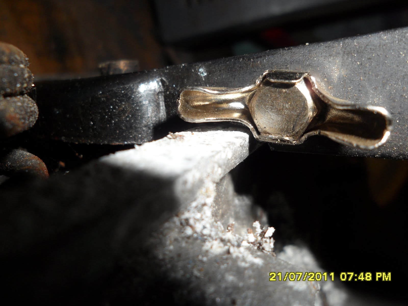
if I could do anything with it. You can see I used my angle grinder to remove to nicks from the very front of the tool so that it would not interfere with the lip on the cylinder head. I then filed it so that it had no rough burrs and was smooth and kind to the soft aluminum head. I found that the scissor action of the clamp was quite difficult yo use. I also found that when you had it clamped onto the head that you could not increase the pressure further by tightening the screw as the bottom of the screw just slid of the head of the valve. This was rather disappointing, however I soon found that if I tightened up the thread hard . I could not close the cramp but I could use a rubber mallet to hit the leaver to make it force the spring to compress. This was a good find as it pulled the spring up tights so that the collets could be removed. The image right shows the top of the tool and how close it is to the edge of the head even with the section removed from the jaws of the compression device. Without this removed the device could not compress the valve enough to allow the collets to be removed. This was obviously a flaw in the design. The collets were then removed and the apparatus was removed to allow the spring to be released. I took the spring and cleaned it up with a wire brush and then wd40. I then placed the new valve old spring and new collets into the head with the same process only i had to balance the device on the compressor before i could compress it this turned out to be considerable easier. The picture right shows the valve inserted in the head and the head pushed onto the cylinder heads. This was then bolted back on turning up the nuts in a diagonal pattern so that it pulled the head up evenly. The newly painted tin ware was then placed under the fan housing and then screwed down tightly. I then inserted the Alternator with the fan still on the back into the housing and strapped it down with the strap before doing up the tin ware screws in this way i could ensure 
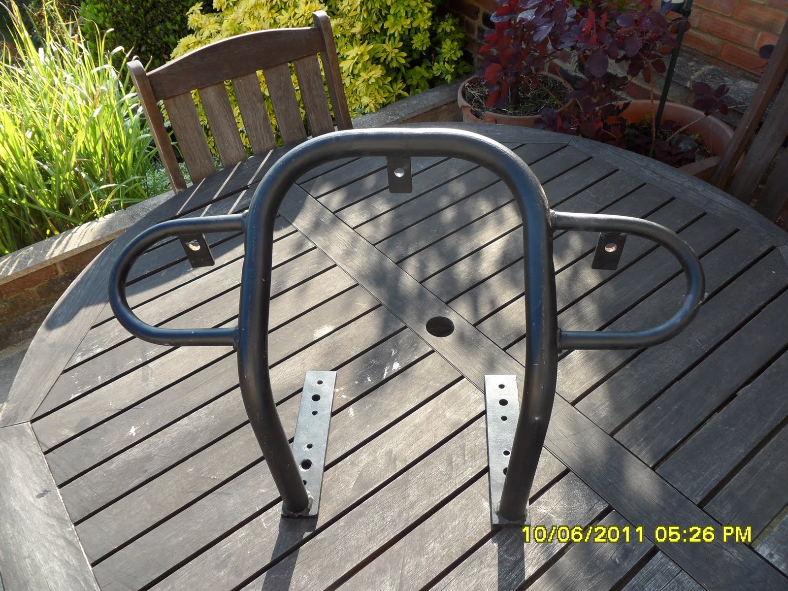
that the fan spun without hitting the housing. I found i needed to pull it forward before doing up the strap to achieve this. When I had the alternator bolted in then I did up the tin ware screws. I then put the carburetors back on using new gaskets . I put the cross bar in whilst the carbs was loose this gave just enough room to get it in so they bolted up with it in place. Whilst I had the engine in bits i Changed my Distributor back to a VAC model and connected up the engine electrics and fuel eager to see if this had changed anything.

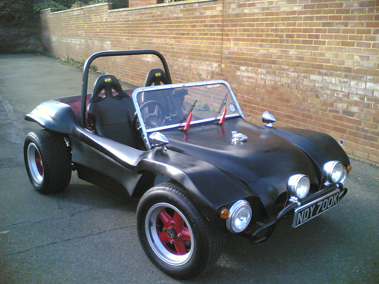
My Buggy Engine running .


The initial run was much smoother and the car ran better. I took the car out for a run

The initial Run


I returned finding that it would not idle when it was hot. I readjusted the idle screws to get it to idle and left the car in its garage to cool down for the evening. I was still very cross with CoolAir Vw they did appologise but I was very upset that they new I needed my parts to get to Bug Jam and there had obviously been a failure in their systems.

Dropped inlet valve spring on no. 2 cylinder

20th July 2011
My engine had been running a little rough and I tried everything I would do normally to get it to run better. I decided that I would have to set down and work methodically to find the problem . I started the Valve timing first steps as detailed already on my blog here, you can find it or many other problems by using the search bar at the top of this page.

It was immediately noticeable that the inlet spring in No2 Cylinder had sheared in half and the spring was held in place in the head. This was a nightmare as I was due to travel with the car on Friday. I knew this was a routine job and had to buy new parts and have them delivered and fitted in two days.

The unfortunate problem of using second hand heads as you can not foresee this type of problem occuring as it is always possible the parts are not as strong as they should be. As everything else was new on the engine this was the weakest part and as such is probably why it failed.

I ordered a new valve compression tool and a couple of valve springs and collets that would come the next day. I did not know if my Valve, piston or cylinder were damaged.

This would really be a test of my skills and covering new ground on this blog I would have to replace a valve spring. Bug Jam was looking like it was evaporating as my chances of going were looking slimmer every minute.

I started in the afternoon to take the engine down starting with the exhaust comming off first on both sides and then the carburetors an linkage. This allowed the screws for the tin wear and fan housing to be undone. With the engine in the car there is no way to remove the fan housing unless the oil filter is undone so i lifted up one side to allow the engine head tine wear to be taken off the one and two cylinders. This then gave access to the cylinder head. The eight bolts were then undone and the head could be pulled off. The top of the piston was ok and the spring damage was now very visable.

Fitting Side Pods

16th July 2011

The day had had a rainful start and for once I could not say I didn't ask for it . I had pitched my tent in the garden to see if it would leak hoping it would rain to test it. I just had not bargained for the torrential rain that came down in the morning, all though this was good to test the tent it was not good for the car as I still wanted to improve some items before the Friday Deadline . Time was disappearing fast and I had a few jobs to to before I would be happy with the 200mile trip to Bug Jam 2011 I had ahead.

I had previous sprayed up the side pods and although had not completely made my self happy with the finish I wanted to fit them to ensure that they fitted after the alterations.

The side pods are GP side pods that I have cut about and now made my own as they were now 80mm taller than they originally was. It was my intention to fit some side air scoops but I thought that I would probably do this at a later time. The stainless brackets I had manufactured and used before where excellent and I managed with a struggle to get the side pods fitted. I fitted the side pods on with three bolts but thought that I would add some more later in the week if time permitted.

I also started to look at my temperature gauge which was not reading correctly after I had bought another sender having lost my VDO original. The new Sender was a Lucus SNB16 and was up to 180 degrees C it gave a resistance of 1.507 K Ohm at 15 degrees C. I knew my gauge was a VDO temperature gauge but could find no documentation for it I figured if I had a 1k pot I could put it inline with the sender and calibrate the temperature to my car temperature gauge for ambient temperature. I hoped I would have time to do this before Friday. I was also starting to work about the petrol cost for the some 400 mile round trip and figured it would be about £100.00 for the cost of the petrol to do the trip.

Solving poor acceleration problems whilst out.

15th July 2011

I decided that I would renew my accelerator cable before bug jam and this is such an easy procedure I will not cover it here. I was still having battery charging problems and also renewed my alternator wire to the starter motor. This was really because the old wire was to thin and had been burnt on the exhaust. I had to jump start the car so I went to a friends house to see if he wanted to come out with his buggy to drive about and test the vehicles and check for any potential problems. As I arrived at his house in the buggy I had experienced some problems on route with the car bogging down. It felt as if I was never getting first and second gear unless I was stationary first. I decided to check the coupling between the gear shaft and the gear box. I immediately noticed that the screw that locates the coupling was loose and the coupling was spinning on the gearbox selector hockey stick arm. I tightened this up and borrowed a battery. This two was flat and again a jump start was needed. We went up to get gas in the cars and again the battery was still week. A Jump start got it going and we ran the two cars for about an hour and one half. I would have to check the battery the following day after our run.

There is nothing to describe the adrenaline rush of driving a buggy on the road and every time i do I get a huge rush that lasts a couple of hours afterwards. I was so happy to have my buggy on the road and although still had to improve the engine running and quieten the exhaust . My Bug Jam ticket had been booked.

Sucessful MOT and miscellaneous engine and steering issues.

14th July 2011

I had took my buggy into Leaders my MOT station at 10:20am on Tuesday 12th July 2011 . To be honest I had to nurse my engine all the way and eventually arrived on time. The MOT went fairly well but my wheel on the nearside was hitting my chassis and a rear bearing nut was loose so initially my car failed on two points which I felt was quite good considering the car had been into complete bits. I corrected these small problems quite quickly the Steering box on my new beam had no stops and it had been bolted in with the stop on the front working but not on the rear. I unbolted the steering box and rotated it. This was much better and I tightened the rear hub nut . My buggy passed the MOT that afternoon.

When I got the buggy home I realized I had not torqued up my Torsion Arms I torqued the Allen machine screws and the locking nuts both to 33 kg/ft 4.5 kg/m. I had noticed that one of the arms was pulling out. Once torqued these felt much more solid.

Now anyone knows who has built a car and has just got it running on the road, this is were the real problems start to be ironed out. My engine was not running very well and I decided to change my distributor back to an Bosch 009 unit as this had run on a car before. This improved the engine somewhat. I then re-timed the car at 30 degrees advance at 3500 RPM . Again there was another small improvement in performance. I then adjusted the linkage bar as I had noticed it was a pulling more on the drivers side carburetor bank. The car seemed to be a little happier.

My Fibrefab SWB RAT 1600 Twin Dell DRLA 40
with Engle 110 cam


I took the car onto some rough ground to see how the suspension handled. The car seemed to run quite well. The next few days would be a constant battle to improve the cars performance tweaking the linkage kit and trying diagnose the problems with my SVDA distributor. Would all these issues clear before Bug Jam 2011 and my car be capable of making the trip.

Fitting Spot Lights

11th July 2011

I had purchased some Spot lights on Ebay that where listed as stainless spots only to find that when they arrived they had been listed incorrectly and where chrome plate . I was a little annoyed at this but felt as I had paid such a low price I would not benefit from returning them to the seller and decided to fit them.

The lights came with earth wiring so I was able to run a short 27amp wire from the earth point for the headlights that both lights could share. I placed two switches in the dash so that the spot lights could be turned off saving the battery I bought these from a small company called "Car Crazy" these fitted through a 10mm hole. I was very pleased that matched the VDO gauges quite well.

I had researched the wiring and felt that I would be best to wire the lamps up with a relay. This would also mean that I could easily rewire them to come on with the main beam only by swapping one wire. I ran a feed from the fuse box to the switch and a earth from my earthing block to the switch. I then needed to get some of the 6mm female spade connectors with a hook on them. I found these on Ebay and was able to solder wires onto them I new I needed short 27 amp wire from the fuse box to the relay and one 27amp wire to run to the lights . I used 8am wire to provide a earth to the relay coil and my switch output was wired to the other side of the coil. These spade connectors where then connected onto the relay on their respective pin position. This enabled me to then take a wire off at a time note its position and push it in to the fuse box. When all four wires had been pushed in the relay could be put in position. I then ran the main feed wire from the relay down the front of the car alongside the wiring for the headlights . I decided to place a connector here so the the lights could be removed. I wired up the lights to these two connectors so that I could try them out . They functioned well with the switch. I decided to then change the wiring the main power feed to the switch instead of powering it from the fuse box bower fuse two I moved it on to the high beam fuse position . This meant the spot lights would only come on with high beam.

My M.O.T was booked for the coming tomorrow I was anxious to know what this would find.

To Low, Beam Spindle choices

9th July 2011

My MOT was becoming very close and my suspension was appearing to drop when I took the car out onto a bumpy track. The syptoms where very strange as if i used the adjusters to set the ride height of the car so that the wheels did not come too close to the wheel arches, the car would eventually return to sit25mm under the arch. This gave no room for suspension travel and I was finding it hard to understand what was happening. I decided that I would remove the dropped spindles and replace them with the spindles from my old beam. sent the spindles off to have them blasted and zinc plated and received them back four days later.

Whist I was waiting for the spindles to be returned I decided that I would cut an inspection hatch into the tunnel so that the process of changing clutch cables could be achieved without having to take the peddle set from the car. I marked the area onto the tunnel and cut the bitumen off of the area . I then cut a hole above the accelerator lever 70mm x 55mm with an angle grinder. I found it easier to cut the corners by drilling out four 8mm holes first. This have me a nice rounded edge that was kinder to your hands. I cleaned the edges with a hand file and The hole was directly over the clutch lever inside the tunnel. I made a stainless plate approximately 20mm larger on each side to cover the hole. I drilled a hole in each corner to take an 8mm bolt. I then bent the stainless sheet with a towing bar in a vice to make the curve profile that would be the same as the tunnel. I then used the stainless cover to mark out a further area on the bitumen this was removed so that the stainless cover could fit flush onto the tunnel I then drilled through the cover plate into the tunnel with an 8mm drill . The cover plate was removed and the holes where enlarged to 12mm so that a spirulux nut insert could be fitted.When all four of these where fitted the cover plate was bolted onto the chassis.

My Spindles had turned up and I was all but ready to fit them onto the car when I noticed that my EMPI long travel ball joint covers where breaking down and had gaping holes in them I was amazed at this as they had been fitted less than four months ago . I contacted my supplier Cool AIR VW and happily they agreed that the ball joints covers where faulty. Cool AIR VW agreed as a kind Gesture to upgrade my cobbers to the German High Quality BTT ball joint covers. These arrived quickly a few days later and seemed to be much thicker rubber. Could not however fit the spring retainers that came with the BTT covers as they where so strong they looked as if they would cut the rubber cover. I opted to use my existing spring retainers as these fitted much more easily but where very secure.

The picture left shows them fitted onto the car.

I then was able to fit my spindles, disk and wheels. These fitted back with no specific problems . I was pleased I had removed the spring located at the back of the SWAY AWAY and thread locked it in place.

The Car was then left overnight on its wheels . The following day it had not sunk down on the suspesion and seemed to be set at about 3" or 100mm of gap between the wheel and the tyre. I phoned and booked a MOT for the next Tuesday and was looking forward to having the car back on the road. I thought I might tackle the front spot light wiring before this as I felt it would be good to have them working.

Facet Pump Problems

1st July 2011

My new Facet fuel pump arrived a few days later and I fitted it into the buggy in several different locations. It was soon obvious that having mounted the pump on the engine that the pump was not capable of pulling fuel from the tank. It seemed as though the only way it could be made to work was to site the pump under the tank. Although I had previously wired pump electrics into my wiring whilst rewiring the car this was really intended to run a much higher pressure injection pump. I had also placed in place the brackets for this so I was not very happy with placing this pump in this position especially as a lot of this would need to be removed. I decided especially as this was supposed to be a quick fix that my only options was to replace the stock pump.

It is important to realize when using the electric pumps that the Facet range are only PUSH pumps ans not PUSH-PULL like the original equipment. These means that placing a Facet Pump is vital as the petrol acts as a coolant to the pump. even the basic pumps will seem to pull up petrol but will not provide enough fuel and will in my experience eventually burn out.

Facet Pump and Regulator problems

29th June 2011

With my engine refitted to my buggy I was getting close to MOT time.

My first problem I noticed was that the FUEL pressure was two high and I needed a regulator to bring this pressure down to the 3.5psi that my carburetors would run on. This should have been a straight forward exercise but to be honest took a lot longer to acquire than I thought. My first purchase did not turn up and the seller refunded my payment the second pump turned up and it was a high pressure Malpasso pump that would not provide a low enough flow rate. I decided to keep this as I felt my 2L engine I had in bits would benefit from this. Finally I decided to buy a new regulator from VW Heritage as i felt this was the only way that I would solve this issue. I kicked my self as I sold my last regulator and vowed not to sell this one. With the regulator fitted my engine ran up and ticked over quite well if a bit rough. I decided to get some more fuel and return to adjust the clutch which was a little high . I tried restarting the car after this and the fuel pump would not run!

Having decided that the mechanical pump baker lite bearing was not going near my car again after fishing bits out of my case twice I had fitted an electric pump a Facet POSI-FLO EFP-3 I name and shame it here as it failed even before the car made it on the road. I cannot believe the reliability of this pump and have now had to purchase a new pump which again with some trepidation is a Facet also. The Facet Silver top pump is made out of metal and seems to relieve better reliability reports in message areas on the Internet . I only wish I had researched this first pump choice better. I hoped it would be more reliable.

I was hoping the new pump would turn up in a few days. I also have been told that this pump needs to be mounted vertically with the filter at the bottom as this is the manufactures suggestion. S next time I will be making a stainless bracket to do this.

Making a reinforcement rear body support bar

25th June 2011.

Having managed to get my front bumper to fit I decided that in the light of my fuel regulator not turning up I would have to finally get round to building a new rear body support. This would be version two as the previous rear support although strong interfered with the position of my exhaust and I had to remove it . I decided that I would try to make the new support so that it could use one of the existing chassis mounts. I choose the mount nearest the shock absorber mount as this was quite near the body work and had a clean flat position near the body work. I bought some 40mm X 8mm stock mild steel 4m which I had cut into 1m 1.5m and 1.5m so that I could get them home from the steel suppliers. This was similar material I had successfully used on the front bar.

I started fabricating the bracket by measuring the distance from the bracket to the body work. This enabled me to make a piece up that would reach onto the body. I welded another piece onto this at right angle so that it would come out from the bracket and run flush. I placed this on the body work and measured the mounting hole coming through the chassis. This fixing was a M10 fixing so I drilled a 1.5mm hole in the bar. This could then be bolted onto the mount. I then used a different piece of bar held horizontal to work out the height that i wanted the bracket to be on the body. I welded this on and made another bracket mirroring the first. I tried to bolt this on but found that the body work was concave and not flat and therefore the body was sitting away from the bracket by some 25mm. I would need to bend the bar to make it follow the shape of the body work. This turned out to be more simple yet more involved than I anticipated. I first of all tried to heat up the bar, this could not get the bar hot enough to even start a bend. I eventually found three 22mm tubes and used two of them one side of the bar and one the other against the metal in a vice. The vice could be then be tightened to bend the metal work. I put three of these bends into the bar and repeated this on the other bracket. With the side brackets made I bolted them onto the car and measured the width of the body work to create a join between the two side brackets i measured this as 94cm and welded a bar on. I also added some small tabs to the side bars so that I could add an under seat support bar. I then tried to refit the bracket and to my dismay found that even with the 80 mm body lift kit there was not enough room to get the bar in without removing the engine. I decided the only option was to cut the bracket in half and lap another piece of 40mm x 150mm to splice the two pieces with bolts. I welded this to one half of the bracket and drilled the other half whilst the bar was still together before cutting it through one side. The resulting two bars then were fitted to the body work the bracket had to be pulled into the body work to allow the two bars to meet. The next problem to overcome was how to drill the body work behind the fan housing to get the bolts through the bracket and fibre-glass. I found that I could heat up a small wood working bradel and use this hot to push through the bar into the the fibre-glass marking the position of the hole as this would push tight through. I could then frill the holes from the inside of the body work. With the brackets mounted I started to fabricate the cross bar . This was made by measuring the distance between the two drop down brackets a length of 935mm bar was cut and some 90 degree up-stands welded on each end. This was then drilled so that it could be bolted to the tabs. I then took the brackets of and painted them with Acrylic black paint before refitting them to the car.

Whilst I was making this bracket I also found some Stainless steel and made a bracket for my front number plate. I made this is in a similar construction to my rear plate. I used an angle grinder to cut the perimeter after drawing around my number plate. I then drew diagonals onto the square plate so that I could drill the corners of the intersections. This meant I could then use the Angle grinder to cut out the inner triangles from the plate making it lighter. I then bent a piece of stainless steel 10" long x 4" this was then bolted onto the number plate backing and protruded enough over the bumper to allow two bolts to be used to bolt it securely on. The finished plate was then cleaned and thick number plate pads where used to secure on the the number plate.

I was still waiting for my fuel regulator to turn up it was the second one i had ordered that had not so far turned up and I was beginning to despair at eBay this rendered my engine not running and I was beginning to worry about time. I found out shortly later that the seller of my item only ships out Saturday morning. It would have been useful to have known this when buying. Hopefully this does mean that it should be with me by Wednesday latest.

Converting my Buggy Bumper or A-Frame use

18th June 2011.

I had previously bought myself an A frame so that I could tow my Buggy some time ago only realizing that it would not fit with existing bumper as it went right to the edges of the beam clamping in exactly the same location as the A-Frame needed to fit. With the beach buggy coming along nicely and the need for a new MOT looming I decided it was time to remedy this problem as I needed a location for my front number plate.

My existing bar was some 3 ft wide and exactly fitted inside the beam with bolts holding on a rear bracket to the beam. Clearly this fitting was not going to work and looking across the beam there was not much option or placements that the bumper could fit onto. The only possible location seemed to be the beam mounts and these were way to narrow. I took some photographs of the beam and tried narrowing it digitally to see how it would look if it was narrowed enough to bolt onto the beam mounts. This didn't seem to look to bad and looked a little like a four by four bumper. Fortunately the loops on the side of the original bumper gave the reduced width version more width. I cut the bumper in half and re-welded it up with an inch bar inside it for strength. This I then made bolt on to the top beam mount and go over the lower Allan Cap bolt the idea being that the bumper could be removed without dismantling the whole beam. This seemed to fit very well and with the lights refitted to the bumper the difference didn't seem that noticeable but the car could now be successfully A-Framed as the mounting points where totally clear. I was not prepared to wire up the lights at the moment as I had not decided the best wiring from them whether it be with the main lights or separately. I felt a seperate switch and feed was the best solution but was unsure if i needed a relay. The next job was going to be fitting a new square number plate onto the front bumper and sorting out some problems with the engine running.