Search This Blog

Showing posts with label Body Lift. Show all posts

Finalizing my position for my Roll bar

30th April 2011

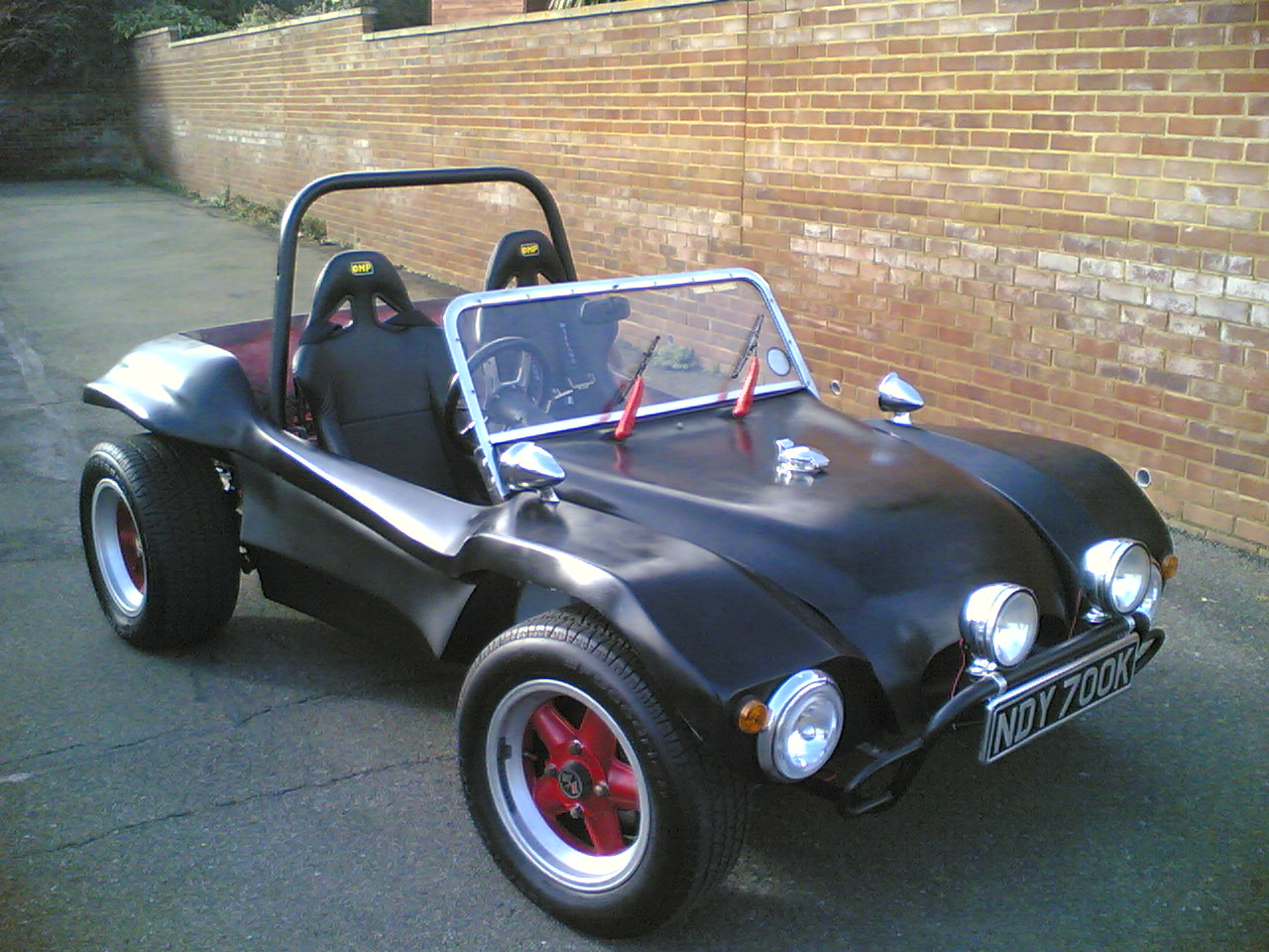
Whilst I awaited my four coats of lacquer to go off hard I decided to get on with the fitting of the roll bar. This was to be moved as far back as it would go as my winged seats hit the old position when the seat was fully slide back. I therefore placed the roll bar right against the new 80mm body lift frame meaning that I could use a bolt through it for stability and eventually tie the two pieces of steel work together. The new position also did not sit on the fibre glass making it much stronger. The only problem with this position was that the rear hoop sat on the back neopolitan's hat so that the front bolt position hovered 20mm above the floor pan. I decided that I would need to make two pieces of steel to fit under here 20mm x 60mm x 55 mm. This would slip under the front tab and work better that washers to provide a solid base for the hoop. I placed the hoop in its position so that I could drill down through the chassis with an 11mm hole. I also drilled horizontally through the 80mm lift tubing so that I drilled its position to be able to drill right through the hoop. I repeated this for the other side and then removed the roll bar so that the body work could be left to dry. I would fit the 20mm x 60mm x 55mm blocks when the body was bolted back in place. Whilst the bodywork was still removed I used the 11mm drill to clearance the holes holding the body lift frame to the chassis. I checked each bolt would pass through without any restriction. I had sprayed the bonnet and side panels in black base coat when i sprayed the flake onto the body work . This did not require 2k Hardener so as I was running short and had used nearly all of my 1 litre of hardener up .

I decided that as I had to buy new hardener the with little I had I could spray the gold flake onto the bonnet, the dashboard and the side panels. It was quite difficult to match the same amount as I had put on the body work but hopefully have got a good match. The side pods came up surprising well but I managed to loose the station tube out of the end of the spray gun head and this put droplets of lacquer on the right hand pod. I guess even after spraying the whole body there are still things to learn about this gun. I have to wonder how much more there would be with a devilbliss or professional HLVP gun. I was however pretty pleased with the results of the Earlex PRO HV5000 spray station it had survived the spraying process and to be honest not done a to bad job. I still had 7 coats of 2k Acrylic lacquer to spray on all of the gold leaf components this left six on the bonnet,dash and side pods and four on the body work. The rest of the evening was devoted to moving some of my car parts to my new garage I had found. This hopefully would be a new base for the buggy and would provide a new site to reassemble all the components. I had one dead line in my mind this year BUG JAM I hoped I would have the car back together with an MOT this was only two months away and although it had took a day to disassemble the parts I new it would take much longer to assemble the parts despite the time needed to put the rest of the lacquer on the parts.

Paint costs for the paint, lacquer, flake, primer costs was mounting up and currently was at £379.00 just for the supplies, this was quite astonishing. I would discuss this in a later article when the painting was completely finished.

Increasing the hieght of my GP side pannels by 80mm

19th April 2011
I decided that after working on the bonnet of the buggy so successfully I would increase the height of my side pods myself.

I have also noticed that this month we have reached 11,000 visits which was fantastic. Please comment or follow this blog by clicking the follow button in the right hand side if you like my blog to give me feedback.

I decided the best approach to this was to use a marking gauge to mark off 15mm along the bottom edge of the side pod. I then used an angle grinder with a thin cutting blade to cut of this section. I made pieces of wood up to space the 80mm gap for the new height, this was checked again along the whole length of the cut before I started to fibre glass up the gap.
I used a piece of plastic cable trunking to span the gap I cut this out of a 4" box so that I just had a flat piece from the side and laid it into the gap using resin to adhere it. I then used fibre glass matting to cover the whole area on the inside of the side pod. This made a very strong joint which enabled me to remove the pieces of wood I had used to separate the two sections. I then used more plastic I had cut out of the box to make up the inside where the pieces of wood had been. You can see from the picture right that this made the side pod rigid especially when the side pieces where fibre glassed in place. The surface of the side pod now had a channel running through the front of it. I couldn't make up my mind what to do with this channel but for speed I used fibre filler P40. to fill the gap up . I had previously used this with good results and found that four 600ml tins was just enough to fill the two channels on both side pods. The picture right shows the channel filled with p40 and the reverse side of the other side pod fibre glassed over the plastic cable conduit. The P.40 had filled the gap nicely , however it gave a very ruff surface . This was rubbed down with 80 grit sandpaper to bring the surface back to a flatter finish . I then used p.48 body filler to fill the surface of this area. You can see from the picture that the side pods are starting to take shape . More sanding was then required to flat off the surfaces. When I was reasonably happy with the outside I painted the inside of the side pods with Hammerite Hammered black paint. This I had found was quite durable and made a much cleaner finish. I then sprayed the outside with High build 2K UPOL Primer filler using a friends professional spraying workstation. I hoped this would be powerful enough to spray the whole car

Next time I would need to paint the body work.

Making front Body Mount & Shutzing bodywork

12th February 2010.
The body work was looking much better on the outside from its fresh coat of hammerite Paint.

I knew that I had to increase the height of the front body mount by 80mm as the body lift I had installed was already achieving this height. I also knew that I would have to move the steering column hole downwards to cater for this rise in height. Fortunately I did not just raise the hole 80mm by filling in the old hole and re-drilling. it seems the height is dependent on a triangulation with the fixed point of the steering box and the bulkhead. I used a piece of wood in the end exactly the correct length to just touch the bulkhead when it was laid alongside the steering box connector. This gave me the correct position of the hole and it seems as I had guessed it was not 80mm from the old hole.

I had made the front bracket originally out of strong material so felt I could bolt onto it a section of 80 x 40 x 3.1mm box. I used hidden Spiralux captive nuts to to enable me to put securing bolts in the middle of the box section. These push fit into a hole and a tool is used to compress the fitting behind the metal so that it makes a permanent fixing. I had already decided to make a bracket to hold the wings firmly this new 80mm area was a welcome fixing site. I bought some mild steel 40x 10mm x 1.5m and used this to lay a section down the side of the box. With this assembly held on with G- crams I was able to see that the location I had picked for the mounts in the wings directly corresponded with this position. I cut two 300mm lengths and two 50mm lengths of the 40mm x 10mm . The 300mm lengths I drilled three holes that corresponded with my mount bolt holes. I was able to bolt these 300mm brackets onto the bodywork. I then used the 50mm x 10 sections to join the two brackets together. This was achieved by cutting slopes on the 50mm piece until it fitted nicely between the two. I then used a clamp to hold the piece in situe whilst it was welded on the car. I repeated the same process for the other side removed the bar and trimmed the back side of the join before welding it on this side. I then bolted the bracket back in position and marked and drilled the bracket so that it could be bolted to the 80mm box. I was surprised just how much I could already feel how much stiffer the wings had become. I remembered my friend Jon having pulled over in front of me some time ago as he thought I had flashed him as we was driving over rough ground with him in front.

I had decided with some advice from a friend Jon to Shutz underseal the inside of my bodywork so giving it a slight texture before it was spray painted. I had used a Shutz underseal gun previously to coat the engine tin ware quite successfully and new that it was s good way of covering uneven surfaces. I bought a bottle of Shutz underseal from my car paint supplier and set about cleaning up the inside of the body work with an Electric DA. I masked the lip of the body so that no Shutz would come onto the body work and started to shutz the inside. The Shutz covered very quickly and soon I had the whole inside bodywork covered. I left this to dry. I had to use my friend Jon's compressor to get the Shutz gun up to its working pressure. I found that one bottle just covered the interior of the buggy, although I felt it will probably need a further coat. With the buggy sprayed with Shutz it was left to dry for some time before it was put back onto the chassis. I knew I would have to make a new bracket up for the dash board support to the steering column and felt that this would have the potential to mess up the new surface . As I needed a second coat of Hamerite and shutz I felt the best option was to mount the dashboard inside the car and manufacture a bracket that would hold the steering column as with this made up I new assembly would be easier and not damage the paint surfaces.

Bodywork improvements - two

6th February 2011
The body work was looking very much better. I decided that I needed to do a little more work on the body work to make a tighter fit to the body kit that I had fabricated as the work I had previously done on the rear was a major improvement. This adjustment process was a great deal easier than trying to fit the body work to the chassis as had been done before as the body lift kit could be placed on the upside down body work allowing easy measurement of the gaps . The front of the bulkhead did not fit tightly and fibre filler was used to bring these areas slightly over the size required so that they could be cut back. Both sides where increased so that there would be approx 4mm off-standing max. The back area was also sanded to make a crisp mating surface for the body kit. The driver side rear quarter also had a slight bulge in the fibre glass and this was sounded out to ensure both sides of the body work was the same when viewed from the rear of the body work.

With the new filled bodywork sanded to fit. I decided to use my remaindering Gray Gel coat to protect the newly fibre glassed areas. This tidied and sealed them up.

I realised that I needed to cut a new steering column hole and could find no measurement of the size of this hole any ware on the Internet . I only had a 51mm cutter so used this but in fact to fit the bush a 48mm or 1" 7/8" hole is required. I new I would have to find a different stronger seal.

The next job was to paint the underneath of the body work. I decided to but 2.5L of Black Hammered Hamerite . This seemed very thick and perfect to coat the underneath of the body work. Fortunately my friend John helped me with this painting as it took over an hour for two of us to paint it. Two coats required 2.5L of paint to complete the underneath. The finish was much better than I had expected to achieve and the whole underneath of the bodywork looked like fresh Fibre glass.

Will probably need to shutz underseal it inside the body work before the next paint coat goes on.

Bodywork improvements - one

30th January 2011
The last day but one of January brought temperatures of 2.5 degrees outside and I knew i had a lot of fibre-glassing to do, which I knew would not be easy to achieve at these low temperatures.

The body work was starting to come along as it was slowly being rubbed down. I had always new that the design of the Fibrefab SWB Rat was very light and that some areas moved when the car was on the road. The worst of these was the front wings and headlights. In addition people for some reason think they can sit on car wings which on this type of buggy is not possible as the wings are not strong enough. With this in mind I had decided that with the body work off I could manage to build a mount that would hold the wings more rigidly. I bought some stainless steel fastenings from an online store these at first seemed difficult to locate as I new i wanted to fibre-glass a block of wood into the wing with some hidden bolts to mount the frame support. The main problem with this is that it is very difficult with a hidden bolt to stop the head spinning when you tighten it. I located some coach bolts that had a square on the underside of the cup. along with this I found some bar that was drilled with 8mm holes in a chain, 205 mm long and 19mm wide. I found that I could make these holes square with a file so that the head of the coach bolt would be captivated in it. I also bought some oak that was wide enough to take a channel to sit this metal work into. I used a router to cut this channel and assembled the two fixings easily. I used a DA to clean the underside of the wing back to the fibre-glass. This would provide me with a location to bolt to on the underside of the wing. I used hairy fibre glass filler to bond the wooden anchor points onto the underside of the frame. After bonding the wooden anchors on by filling the groove up with filler and then mating them onto a bed of filler I managed to build up enough hairy filler to make the bracket slope into the underneath of the wing. I had nearly completed both anchors when I realized I was running out of filler. I would have to wait for this to dry and purchase some more filler to complete smoothing them into the wings.

With the body work upside down I also noticed that the underside of the shell did not mate as well as it could do. I used the the body kit frame on the underneath of the body to improve the angles of the back transom. This was really a try bit by bit operation , which |I must confess was a little easier than mating it to the chassis. used the DA to cut the body work down . It was to high were I had made it up with fibre-glass and improved it significantly by this trial and error approach. There was some areas that needed making up with 5mm of filler so I knew my visit to buy more fibre-glass filler was going to have to be very soon.

With the 1.8ml tub of Fibre filler purchase I started work making up the back section . I knew this was going to be an overnight hardening process so set about making good with the filler using a straight edge to ensure the angles where good and straight . I also filled the center area so that it could be cut back to fit the body kit tighter. You can see the result of using the fibre filler really improved the back section. The drying time for this filler is usually 20 mins and I new as the temperatures was very low that there was not much chance of this drying other than over night.


The next morning I returned and applied more fibre fill to the front wings to smooth out the wing around the mated on block. I built up the edges with fibre fill so that the gradient between the block and the wing was smooth making the block disappear into the fibre glass wing. I new this would take a long time to dry out so left the fibre fiiller over night to really harden up. The smooth finish I would need to coat with a skin of fibreglass mat to seal it in from the weather. I new that the filler would need to harden off and that it needed to be totally dried out before this was applied.

Drilling the 80mm body Lift kit

3rd January 2010
The buggy was housed nicely in a friends garage and the snow was starting to flurry when a call came in this morning.

I got to the garage and we pulled the buggy out . I had decided that the 80mm body lift kit would need to be drilled before it was to be blasted and Zinc plated. This meant it had to be accurately positioned on the bare chassis. So that the holes in the buggy floor pan could be marked with a felt pen. This would have been easy if I had remembered to take a felt pen and my friend had not bought some from the pound shop.

We finally found a working felt and marked up the holes after taking measurements across the chassis to ensure that the frame was central. The body lift kit was then removed and the marks were spot marked with a punch and a hammer. I had previously used 8mm bolts to hold my chassis to my body and after a short discussion we both decided that 10mm bolts would be a better bet. new I would need 22 x 120mm x 10mm to bolt down the body through the body lift kit and chassis.

The position of the bolt holes that had been transferred to the chassis where then pre-drilled with a 6mm High Speed metal drill bit at a slowish drill speed.
Once the holes on one side was pre-drilled they where drilled using larger sizes until a 12mm hole was achieved. The body lift kit was then placed back onto the chassis with the body work on top of it so that the holes from the body work could be marked. These were spot marked with a punch in the same manner as the underneath holes. The drilling process was then repeated leaving a hole on the top and bottom of the lift kit. Once this was done the 12mm drill was then used to run through both holes to ensure that a bolt would navigate through.

With the hoes drilled it was noticeable that the body work looked untidy and overhung the body lift kit. The body work was marked were it over-hanged the lift kit . This was then trimmed off by my friend with a jigsaw so that it neatly sat along the inside. The picture to the right shows the underneath of the body work it also shows the areas that I had cut out to fit the traction bar. I would need to finish repairing these areas at a later date.

With the snow starting to flurry harder we placed the chassis and the body back in the garage and turned our attention to the troublesome engine. There was a large amount of power all over the clutch which looked as if the clutch had been slipping. The clutch cover plate was removed by undoing the bolts that run round the outside of it as the clutch pressure plate came of the clutch plate shattered into bits on the ground. Luckily both the clutch pressure plate and the fly wheel seemed to be unscathed with no damage. I asked my friend if he had a bar that we could try to turn the engine over with. Amazingly the engine seemed to rotate. It got as far as the number one firing position on the distributor and would not go any further. Counter rotating it allowed it to turn freely round to the number three firing position. This seemed very perplexing . We wondered if a gudgeon pin had come out. But the real reason probably would only been seen when the engine was took apart. In the mean time I had to get the body lift kit blasted and zinc plated.

New Year 2011 Strip down

2nd January 2011
My New Year started with a vengeance to find the problems that had riddled my project for six months previous thanks to a great deal of motivation supplied from a very good friend and fellow enthusiast. We decided to first of all remove the engine which had been rebuilt some months before and which had seized in the garage as it had been left for too long without engine Oil. The process I had tried to re free the engine had obviously had a toll on the clutch and clutch plate. The pictures show the power that had been worn off the clutch friction plate.

Once the engine was out we decided that as time was available we would strip the Beach buggy right down to its chassis, in an attempt to see if the body lift kit would fit onto the buggy chassis as it had been previously fabricated on a donor chassis.

The strip down was fairly quick and everything seemed to come apart really easily. I put this down to the quality bolts I had used.

First the seats were removed by undoing the four bolts that went through the floor pan. Once the two seats were removed, it was then possible to get to all of the 8mm perimeter bolts that hold the body work to the chassis. As several of these hold in the Roll Bar these were removed also and the Roll Bar was lifted out. The windscreen and bonnet then had to be removed along with the petrol tank.The next problem to get over needed the front lights and indicator wiring to be removed from the Fuse box. Additionally the ignition wiring harness and the brake light and horn wiring all had to be disconnected. The front body mounts could be then removed allowing the body to be lifted off. The body lift kit could then be placed on the chassis to see if it would fit. Fortunately it did the work I had done in the summer was fruitful and the two mated perfectly. With the body lift kit on, the body work was placed back on to see how the ride height looked. The front definitely needed to have the adjustable beam that I had been rebuilding and I felt this would bring the front down so that the front wheels filled the wheel arches once more. The front seats were placed back into the car temporarily so that the seat height could be checked . The raised height was fantastic just what I needed so that a soft top could be fabricated that would not need a head hole for my head to poke through. A shopping list was then made to acquire longer bolts some and a new 9mm drill so that the body work could be fixed back onto the chassis. As I had taken the body work off I felt that it was in need of a clean up and thought it would be a good idea to fibre glass the areas properly from the underneath where I had cut out the areas for the cross bracing in the rear.

With the bodywork back on it was apparent that the Roll Bar would be very much higher than it needed to be. We found that it would just fit snugly inside the body lift kit. This would allow it to retain its height and could be bolted through the the Roll Bar and the side of the Body Lift frame. This had the advantage of making a strong structure that contained the people sitting in the beach buggy.

It would be some time before the car was back in one piece again.

Manufacturing a body lift kit - part four

19th June 2010
The previous weeks have been very busy and I have not had the opportunity nor the weather to get the body lift kit cut down and welded. Fortunately there was a small break in my time that coincided with reasonable whether albeit raining to all all the rails to be cut down and cramped to the chassis prior to welding.

I had previously spent some time trying to neaten up the welding this actually was costly in time. As when I was improving the welds I found that the heat I had applied to the curves had reshaped the curves so they no longer fitted. The only option was to cut new slices into the rails and re weld whilst the section was cramped to the chassis. This worked very well and it appeared both sides had warped due to this clean up. The picture right shows the cuts that were made and welded up to bring the curves back in line. Once the curves were cut the side pieces were cut to length. This was achieved by placing both front and back sections on the chassis and marking their positions on the chassis. This could then be transferred onto the side bars and the cuts where made to match the profile of the front and back sections where they mated. The front sections where fairly square the rear sections approach the side at a slight angle. This required a 5-6mm angle to be cut onto the side rail. A friend came by who uses a MIG welder and wanted to try ARC welding As I new the outer sections would need flushing I let him try his hand. Fortunately he made a pretty good job.

The welds where soon completed and the body lift frame was left on the chassis to cool down in preparation to a clean down with a grinder. Four end plates where cut out and cleaned up so that they could be welded into the ends of the body lift kit tubing. This would keep the moisture out of the tubes and make the section solid. The perimeter holes would then be needed to be marked from the underneath the chassis and the center punched and drilled. Once the welds where cleaned up the whole body lift frame would be prepped to be taken to be hot zinc sprayed and then blacked. This process was the best way of stopping the steel from rusting as it was used successfully on bumpers and roll bar parts to keep them clean. The process was original developed for 4x4 bumpers as the knocks ride of the zinc coating and the item can just be re blacked to bring it back to the same finish.

The most important thing I found when building this is that the curves cannot be made my bending the tubing. If you try this yourself you will find your body will not fit on top as the top of the tubing curved radius will be different to the bottom. Originally I thought I would have this manufactured at about £150.00 . The materials cost £50 for the 75mm box tubing 3m length. 20 cutting disks £20.00, and 100 welding rods. I would imagine having completed this it would have cost me £350.00 - £450.00 to have had built from the same materials.

Manufacturing a body lift kit - part three

20th May 2010

My welding mask arrived quite quickly along with some rods that I had purchased from eBay . I decided to start welding up the back section first as this seemed the simplest. The three pieces were cramped to the chassis and butted up i ground a V in all the joints so that I could get more weld in them and therefore get a stronger joint. These were soon to run out but luckily Lidl was selling a welder and welding rods I bought 4 boxes on chance for £3.95 they are superb and I am very surprised.

Front and back sections.
I started with the curve in the back section I made very small triangle pieces out of the box section to fill the area between the slits this held the position of the curve and allowed the weld to maintain it self . This was repeated until the whole curve was welded up. You can see from the picture the inner face was smooth as it required no welding whilst the outer surfaces would require grinding. the rear diagonals were all then fitted to the donor chassis and cramped in position so that the rear section could be welded. This proved quite successful I had cut a section out of each side to fit snugly into the rear chassis section. This was all tacked and welded. The middle curve section was then dropped in and the whole section was tacked and then welded up. I was very pleased with the result of this as this was a technically challenging part to make up as it had a lot of curves and bends in its construction. The rear section was then fully welded up and the whole rear section was retried on the rear of the chassis cross member. The next sections would again require cramping the new frame to the chassis. I welded up the curve of each of the front section so that it could check it on the chassis I used thin slivers of cut tubing in a wedge shape so as to not have to infill with so much weld. It was a pretty good fit. The front two halves could then be welded together whist cramped to the chassis. Once the two halves was welded together it was noticeable that one of the lower leg angles had moved due to the heat of the welding this angle was cut back out by using an angle grinder and the new angle was welded together again to make a good fit. The finished version was obviously incorrect as the top curve was totally wrong. I new this would not fit the chassis. I drew an initial template from the bottom of the section. When I superimposed it on the top It was noticeable that the curve needed to be at least another 1/2" higher. I stated fabricating a new top by making a new curve section that would fit the bottom. I made this extend further into the bend so that It would clear the existing welding. This was then welded up to make a solid curve. I was able to then position this on the top of the curve to allow me to mark the union of the two pieces this was quite complicated but surprisingly went very easy. You can see in the diagram left I have cut the two sections so that they mated seamlessly into the curve of the welded front section. The difference in the previous and the new curve is immediately noticeable. I tested this design on the body and chassis of a donor vehicle to my horror the whole top section was still wrong. Further analysis proved that there was a strange phenomenon happening. It appeared as if the sloping sections of the front section had to be thinner than the 80mm box to keep the same shape and profile as the bottom of the front piece. It looked on paper that these needed to be 12.3mm thinner. This was completely unbelievable. But yet with the top lowered 12.3mm the top would again fit the bottom of the section like it should. After a while scratching my head I decided the only reason for this had to be that the slopes vertical diagonal component had to be 80mm and this was the reason the width had to be reduced by 12.3mm. This was a very iimportant discovery as it meant the rear section may not be correct either. The math for this was also simpler than I thought it was basic trigonometry a jotting pad soon came up with the mathematics needed to find the new height required on the diagonal components based on the angle that the diagonal was leaving the vertical. Looking at the rear section this was also wrong and needed changing as clearly the end sections was wrong and not following the contour of the top either.

Front section finalized.
I new that I would have to lower the peek of the front section by 12.3 mm. To achieve this I would need to cut out this new section from the front all the way down to the flat ends. I would then have to remove 12.3mm and re weld the whole assembly back up . The picture right shows the top half lowered by 12.3 mm . This gives a vertical height in the middle of 80mm. Which is correct and now fits the body work perfectly. This would also need to be done for the rear section which is a much more complicated section. I would have to work again from the angle to the horizontal and use a trigonometry tan function to work out the new height. One really interesting thing about all of this is that the number of people that told me to get the tubing bent to make this would have all been wrong as this would not allow the body work to fit in the same way as my previous methods had not.

Rear Section finalized.
The rear section was with the new mathematical information also wrong the angle it raised from the horizontal was 20 degrees . Using trigonometry (80 mm/(cos 20) = 85.1 mm ) - 80 mm = 5.1mm shorter in the diagonal heights. It can bee seen from the photo left that the original rear section I had made fitted the bottom beautifully but the ends of the section where wrong and too short on the top section. This meant also the height of the tubing needed shortening by 5 mm. I started by marking out the cuts to each side diagonal and the increase in end required. With this I was able to cut the top of the diagonals and shorten the box tubing by 5mm. This also gave enough distance for the end pieces to be extended.

Two opposing side sections.
The side sections were much easier to fabricate to shape I cramped the side sections to the chassis and ensured they matched the curves in the chassis. I ensured that the lengths where longer than I required so that they could be trim to size. I cramped the rear section first and then moved forward placing new cramps to ensure the shape was correctly held in place. Some gaps where to large to weld so I used the cut out triangles from the rear section that I cut out and welded them into the larger gaps. This process yielded a much cleaner weld and it can be seen that it held the section together better. With this repeated for both sides the design was starting to come to shape. I tacked both sides so that they could be transported and welded up in a warmer environment. You can see with both sides cramped in situe the strength of this new section was already stiffening up the chassis. The picture left shows the two side sections tacked together before they were removed to be fully welded.

This was becoming a lot more complicated structure to build than I had figured I would need to cut the sections to shape and weld them up to make a complete chassis. This will be continued in the next episode.