Search This Blog

Showing posts with label Fabricate. Show all posts

Manufacturing a body lift kit - part three

20th May 2010

My welding mask arrived quite quickly along with some rods that I had purchased from eBay . I decided to start welding up the back section first as this seemed the simplest. The three pieces were cramped to the chassis and butted up i ground a V in all the joints so that I could get more weld in them and therefore get a stronger joint. These were soon to run out but luckily Lidl was selling a welder and welding rods I bought 4 boxes on chance for £3.95 they are superb and I am very surprised.

Front and back sections.
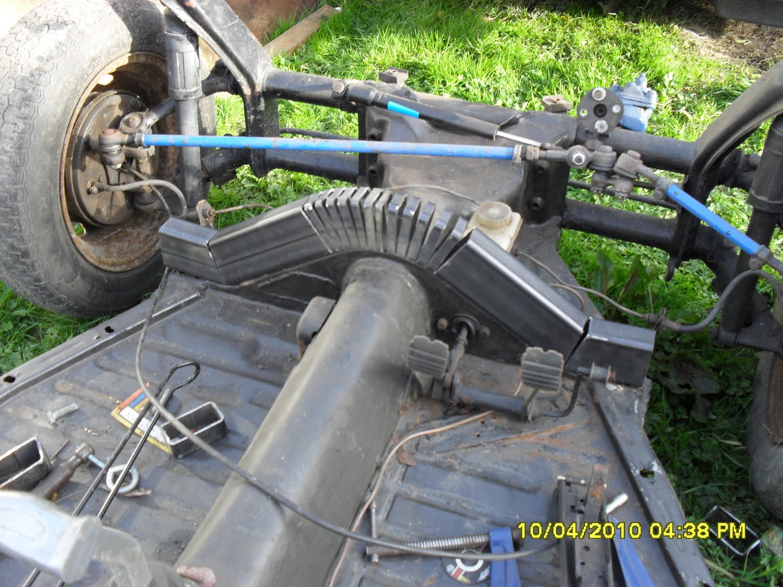
I started with the curve in the back section I made very small triangle pieces out of the box section to fill the area between the slits this held the position of the curve and allowed the weld to maintain it self . This was repeated until the whole curve was welded up. You can see from the picture the inner face was smooth as it required no welding whilst the outer surfaces would require grinding. the rear diagonals were all then fitted to the donor chassis and cramped in position so that the rear section could be welded. This proved quite successful I had cut a section out of each side to fit snugly into the rear chassis section. This was all tacked and welded. The middle curve section was then dropped in and the whole section was tacked and then welded up. I was very pleased with the result of this as this was a technically challenging part to make up as it had a lot of curves and bends in its construction. The rear section was then fully welded up and the whole rear section was retried on the rear of the chassis cross member. The next sections would again require cramping the new frame to the chassis. I welded up the curve of each of the front section so that it could check it on the chassis I used thin slivers of cut tubing in a wedge shape so as to not have to infill with so much weld. It was a pretty good fit. The front two halves could then be welded together whist cramped to the chassis. Once the two halves was welded together it was noticeable that one of the lower leg angles had moved due to the heat of the welding this angle was cut back out by using an angle grinder and the new angle was welded together again to make a good fit. The finished version was obviously incorrect as the top curve was totally wrong. I new this would not fit the chassis. I drew an initial template from the bottom of the section. When I superimposed it on the top It was noticeable that the curve needed to be at least another 1/2" higher. I stated fabricating a new top by making a new curve section that would fit the bottom. I made this extend further into the bend so that It would clear the existing welding. This was then welded up to make a solid curve. I was able to then position this on the top of the curve to allow me to mark the union of the two pieces this was quite complicated but surprisingly went very easy. You can see in the diagram left I have cut the two sections so that they mated seamlessly into the curve of the welded front section. The difference in the previous and the new curve is immediately noticeable. I tested this design on the body and chassis of a donor vehicle to my horror the whole top section was still wrong. Further analysis proved that there was a strange phenomenon happening. It appeared as if the sloping sections of the front section had to be thinner than the 80mm box to keep the same shape and profile as the bottom of the front piece. It looked on paper that these needed to be 12.3mm thinner. This was completely unbelievable. But yet with the top lowered 12.3mm the top would again fit the bottom of the section like it should. After a while scratching my head I decided the only reason for this had to be that the slopes vertical diagonal component had to be 80mm and this was the reason the width had to be reduced by 12.3mm. This was a very iimportant discovery as it meant the rear section may not be correct either. The math for this was also simpler than I thought it was basic trigonometry a jotting pad soon came up with the mathematics needed to find the new height required on the diagonal components based on the angle that the diagonal was leaving the vertical. Looking at the rear section this was also wrong and needed changing as clearly the end sections was wrong and not following the contour of the top either.

Front section finalized.
I new that I would have to lower the peek of the front section by 12.3 mm. To achieve this I would need to cut out this new section from the front all the way down to the flat ends. I would then have to remove 12.3mm and re weld the whole assembly back up . The picture right shows the top half lowered by 12.3 mm . This gives a vertical height in the middle of 80mm. Which is correct and now fits the body work perfectly. This would also need to be done for the rear section which is a much more complicated section. I would have to work again from the angle to the horizontal and use a trigonometry tan function to work out the new height. One really interesting thing about all of this is that the number of people that told me to get the tubing bent to make this would have all been wrong as this would not allow the body work to fit in the same way as my previous methods had not.

Rear Section finalized.
The rear section was with the new mathematical information also wrong the angle it raised from the horizontal was 20 degrees . Using trigonometry (80 mm/(cos 20) = 85.1 mm ) - 80 mm = 5.1mm shorter in the diagonal heights. It can bee seen from the photo left that the original rear section I had made fitted the bottom beautifully but the ends of the section where wrong and too short on the top section. This meant also the height of the tubing needed shortening by 5 mm. I started by marking out the cuts to each side diagonal and the increase in end required. With this I was able to cut the top of the diagonals and shorten the box tubing by 5mm. This also gave enough distance for the end pieces to be extended.

Two opposing side sections.
The side sections were much easier to fabricate to shape I cramped the side sections to the chassis and ensured they matched the curves in the chassis. I ensured that the lengths where longer than I required so that they could be trim to size. I cramped the rear section first and then moved forward placing new cramps to ensure the shape was correctly held in place. Some gaps where to large to weld so I used the cut out triangles from the rear section that I cut out and welded them into the larger gaps. This process yielded a much cleaner weld and it can be seen that it held the section together better. With this repeated for both sides the design was starting to come to shape. I tacked both sides so that they could be transported and welded up in a warmer environment. You can see with both sides cramped in situe the strength of this new section was already stiffening up the chassis. The picture left shows the two side sections tacked together before they were removed to be fully welded.

This was becoming a lot more complicated structure to build than I had figured I would need to cut the sections to shape and weld them up to make a complete chassis. This will be continued in the next episode.

Manufacturing a body lift kit - part two

10th April 2010
As I started to ponder the front and back sections of the body lift frame. I realized as I looked at the chassis that there was in fact more curves than I had originally seen when I appraised these sections. Specifically at the back I had tried to cut a section to fit the side rail by using a bevel gauge to find the angle. On revisiting the chassis it was evident that this was wrong as there was a very small angle 20 degrees at the end of the rear run sections that made the tubing hit it when it sat square along the chassis. Obviously this affected the way it was constructed. I cut the length of each diagonal on the rear of the chassis at 55mm which allowed a small overhang so that it could be trimmed when I had cut the curved top piece to make it fit flush for welding. I then measured 50 mm up each length and marked a center point to cut a triangle out to make the lower angle using trigonometry (tan 20) * 80 mm I worked out the base would need to be 28 mm. I measured and cut this triangle section out and bent the metal to form the correct angle . The curved section that sat around the access panel for the gear lever linkage was going to need to be created entirely on a curve. This would prove to be one of the most difficult pieces to get correct as there was no way to cramp it to the chassis to hold its shape like I had done with the other parts to weld them. The process of getting this curve took some time to get correct as it had to be accurate as the brake line ran directly behind it. I cut the back inspection plate curve at 20 mm intervals there was twenty cuts needed to form the semi circle curve. The rear section bottom angle was made by cutting one 30 mm piece out of the top edge of the box centered on 50 mm from the end of the tubing this gave enough material to be removed to create an angle of 20 degrees. The mitre between the diagonal upright and the curve section was very difficult to get to fit neatly luckily I had a very good friend John to help me and we eventually managed to get a reasonable fit. The front box section I decided was going to be needed to be constructed in two sections. The reason for this was it would be easier to construct two curves each side instead of four in one piece of box section. This allowed for the pieces to be cut and marked so achieving a good curve going over the tunnel that represented the original as much as possible. The lower angle approaching the tunnel was measured at 35 degrees using trigonometry (tan 35 degrees) * 80 mm I calculated that a triangle of 58 mm on the top base edge was required . I then cut slits at 10 mm intervals to allow the rest of the metal to be curved. The front two sections where then cut so the butted up to each other in the center. as you can see at this point the front and back sides had not been trimmed to length. I decided that the two curves front on back were stable enough to be welded off the car chassis. This was good as I wanted to get some experience of welding this material and in filling the gaps I had created with the slits. I knew I would need this as when I returned with the welded section sections I would have a large welding tacking job at hand. The picture right shows all the parts cut to shape. Some of the parts would need to be shortened after the sections front and back where joined together on the chassis. The reason for this was to try to ensure the parts hugged the chassis neatly. With everything cut I was waiting for a replacement welding helmet to turn up so that I could start welding. I was very pleased with the work and the help of my friend both with some of the difficult pieces and the use of his chassis to fabricate this lift kit onto. Whilst waiting for my welding helmet to arrive I noticed that the radius of the curves on the front cross section where different radius's top and bottom of the middle section. This would mean the front section would need the top of it to be remade to the same radius at the bottom. I decided this was something I could do once it was welded.


Manufacturing a body lift kit - part one

28th March 2010.

I had been searching the Internet for a body lift kit that would allow the body to be raised on my Buggy so that the pressure ducting from the turbo would fit under the rear of the body. I had originally considered that I would fiberglass the rear body area , but a good friend had suggested this as another option and it was then I realized it would solve two of my problems, the second being head room. I had really not wanted to change the look of the car to much and after looking at different hood designs I was aware that my head would go through a soft top with the current set up. I had thought that I would have to lower my floor pans to allow the seats to be placed lower than the chassis. This is a large amount of work and the body lift kit idea seemed to cater for both problems. I had found that in America I could buy a BugPack body lift kit. Pictured left. This seemed a little delicate for my off road requirements so I started to source some material to make the lift kit from.

I found a supplier ARC Fabrication Ltd in Hastings that supplied me with 80mm x 40xmm 3.1mm x 1.5m lengths this was ideal as I had been told that I needed four to go around the perimeter of the shortened chassis. I picked up the mild steel box section and started to ponder the best way of fitting it around the complex shape of the floor pan.

There was at least six curves to negotiate and luckily a good friend had a chassis that I could build the lift kit onto and was very helpful through the build process. I had put a thread on VZI asking which was the best way to curve the box section as I new there was several ways of achieving this. The consensus was that bending the material put stresses into the side walls of the material and that cutting and welding was a better option.

I decided I would have to see if there was a mathematical rule for calculating the number of cuts and the distance between the cuts to negotiate a curve. I had been told already that the curve on the leading edge of the chassis near the front needed six cuts that where spaced at 20mm intervals apart to negotiate this curve but had no idea how this had been calculated. This meant I needed to research this as I had to get over the tunnel and this was going to be very difficult without some maths to simplify it.

I started by working on the side rails. Initially these had looked like they only had one curve but in fact they had two on each side. I started by marking the rail were the curve started to come in at the front this gave me a position to start cutting into the rail. I marked the chassis were this mark intersected it so that it could be used as a reference marker to re-align the rail in the same position. I then marked out six cut marks 20mm along each rail, so that the 20mm intervals fell around where the curve was going to come. This gave me my cutting marks. Cut the box section using 1mm metal cutting disks these cut quickly tthrough heavy metal. It is very important to wear safety equipment with these cutting disks as they can easily cut through anything quickly. Three sides of the box section was cut so that it lost its rigidity and was able to be bent around the chassis to form an even curve.I used the 4" C-cramps to initially cramp the longest side onto the chassis. This gave a fixed point so that the the other half of the box section could be levered into position. I used a piece of wooden batten to pull each of the cuts out so making the distances regular and more easy to weld. The process was then repeated for the other side.
It was soon noticeable that the box section cut across the front edge of the floor pan. This didn't look very neat and I decided that if another curve going the opposite was was placed at the end it would bring the end of the box section back in line with the chassis. The angle of this curve was much tighter than the previous one and I decided to make six cuts at 15mm interval to allow for the tightness of the curve. You can see in the picture opposite that the box section now followed the perimeter of the chassis sides. I had only bought with me a few C-cramps and really did not have enough cramps to cramp both sides down hard. The result of this was that I new I would have to return and complete the front and back sections. I had decided to make the front sections out of two pieces and the rear section out of three pieces. The reason for this was to simplify the curves so that the box section would fit flusher with the chassis. I will return to make the front and rear sections in the next article.

Supplier
Arc Fabrication Ltd
Unit 1/2 Bulverhythe Works, Bulverhyth Road, St Leonards on Sea Tel 01424 715220

Manufacturing a buggy rear body mount

29th Oct 2009.
I knew that with the increased engine performance I was adding to the buggy that I would have to strengthen the FibreFab body panels as compared to modern equivalents the body thickness was a lot thinner and lighter. As a result of this I knew the biggest area without support had to be the rear seat area. Since I had cut this to facilitate the CSP Torque bar I knew that it was in desperate need of something sturdy to hold it up. Previously I had fitted a heavy duty cradle and this had a flattened bottom section that looked like it was made to take a 30mm tubular cross beam. With this and some galvanised farm gate hinges I set out to make a strong body rear mount that would fix to the gearbox cradle.

I bought the galvanised gate hinges from a local farm store they were pretty inexpensive too under £10.00 for the pair. I bought some 20mm x 1.5mm x 90mm bolts to hold them together from my local bolt specialist. The 30mm x 30mm x 2mm tubular section on the other hand was something that I was finding hard to locate. My stock piles had long since gone with several moves , eventually I found a suitable item a towing bar that was made from galvanised steel this was exactly what I was looking for. I cut a section of the 30mm x 30mm x 2mm tube 40cm long and held it against the gearbox cradle to mark the locations of the bolt holes.

I packed the farm gate hinges with three zinc plated washers. I used a nyloc nut to secure it all together and cut the end of the bolt to shorten it to 15mm longer than the face of the nyloc nut. I repeated this twice. When I bought the farm gate hinges I bought more nuts than I needed . The reason for this was that I was going to have to grind some of the nuts down so that they were square and would fit inside the inch tube. Once the nut would fit inside the tube four holes were drilled in the 30mm x 30mm x 2mm tubing so that they could be puddle welded. It was immediately apparent that the gate hinges would need more than one support in the 30mm x 30mm x 2mm tube so I started about making three more square washers from the hexagon nuts. This was made easier by using a vice clamp to hold the nut whilst using an angle grinder to flatten the surface. The next problem that I realised was going to be positioning the two nuts in the tube prior to welding and also allow them to thread up OK. I decided the only way to achieve this was going to be to have to drill the locating holes in the 30mm x 30mm x 2mm tube first. This meant putting the nuts onto the thread and spacing them and positioning them on top of the 30mm x 30mm x 2mm tube so that the position for the puddle weld holes could be marked and drilled. With the holes cross drilled the nuts could be reinserted into the tube. The thread of the gate hinge was then used to position them and the nut and the tube was drilled to get a better puddle weld that would penetrate into the nut. The puddle welds were then done on opposing sides so as to keep the tube square. This was repeated for the other opposing sides to secure the two nuts. The same process was done for the other end of the 30mm x 30mm x 2mm tube making the base for the body mount ready to fit. The farm gate hinges would just screw in so that they would provide an angled threaded section up towards the rear seated area. I originally thought that 10mm bolts would hold it but the weight and size of the holes in the cradle has made me consider 12mm or 14mm bolts instead. The 14mm holes were drilled after the picture was taken.

I made the diagonal risers from 25mm x25mm x 2mm square tubing slightly smaller than the 30mm x 30mm x 2mm as its was the material remaining from the towing bar kit. I welded the nuts onto the end of the bar to make an upriser that would reach just below the bodywork. I also left part of the hook that attached the bar to the car so that the nut could be welded firmly onto it I cut half circle sections into one face of the nut so that it would fit the remnant bar and give a good contact area for welding. I felt this should be made of lighter material as the double skin I had used for the base was heavy but strong. I was intending to make a stainless steel plate that would attach this to the body work, with bolts that went straight through the body work.This would need to have a 'U' shaped upstand fabricated onto the bracket to receive the bar. Having bolted on the bars It was soon visible that this would not be the answer.

I contemplated using the sections of larger tubing to make a boltable on end plate that would have the advantage that it could be removed and welded up easily. I was not also sure whether to use an angle iron across the back of the buggy seat area so as to tie the two diagonal uprights together and make a solid section to which things on the seat area could be bolted through too.

I decided after a considerable time looking around to buy two galvanised joist hangers these were fairly heavy duty and I had realised that if I removed one side of the hanger I would have a corner piece that would give me a large enough area to weld on a piece of larger diameter tubing that would slip over the diagonal uprights. This in turn could be bolted together making a strong joint that would give a large mounting area on each side of the body work. The first job was to remove the side of the joist hanger these had been spot welded together so initially I tried drilling them out. I managed to drill deep enough to just remove the weld. The remaining weld could be removed with a hammer and chisel. For a strange unknown reason the second bracket seemed to come apart more easily. The two opposing corner brackets can be seen pictured left without the diagonal bars welded in place. I would have to source some 30mm x 30mm x 2mm square tubing to make the diagonal guides as I only had one piece remaining from the tow bar.

In addition the area the engine was going to come into was becoming quite crowded and I needed to ensure that none of my new pipe work interfered with the engine cylinders or exhaust system. I decided to make up a wooden template that would hang off the gearbox final drive so that the position of the new bars could be determined and then placed on the back of the engine to see if the new metal work impinged on any of the engine before the brackets were welded up. The images show that the wooden template was made from thin fence slats cut down to 35mm wide. The drop from my final drive to the top of the bracket was 200mm. The narrowest point was 23mm from the centre point. I drilled the ends to make the angle adjustable and set it using a gauge to be the same as the angle coming of the bottom bracket. You can see that the bracket misses the exhaust. Phew! With this all checked and the constraints off the engine taken into account the brackets could be welded. It is important to note that different exhausts have different profiles and may extend into this area in different ways. Ensure you check your exhaust configuration in a similar manner otherwise you may not be able to refit your engine..

With both sides removed I trimmed off the surplus material and placed the corner piece on the buggy and slid on the larger diameter tubing so that I could mark the angle that this needed to be welded. This was then repeated to mark the opposite bracket. Both brackets were then removed and the galvanised surface removed for the welding to adhere. They were then welded taking care not to warp the steel in the process. The Galvanized coating was quite difficult to weld even with the surface removed so it was vital an area along the join had to be ground out.

The corner brackets where then cleaned up on a wire brush and the welds thoroughly checked. they were then mounted on the buggy and checked for position. It can be seen from the picture right that some changes had to be made to the adjustment screws to get the angles the same on each side. Originally the left bracket kicked up a little because of the difference in angle. Suitable mounting points were determined and marked so both brackets could be removed so that they could be drilled. 4 holes were drilled into the side plate big enough to take a 10mm bolt. One of the holes went right through the diagonal upright securing it to the body and mount. The parts were re assembled with 10mm bolts. Suitable large washers were also found to stop the body work chafing on the bolt heads. Ideally the items should be re zinc coated. The finished mount was very strong and could take a heavier load in the rear seating area. It also eliminated the flex that is inherent in fibre glass body panels.

The next step would be to ensure the gel coats were added to the newly fibre glassed areas prior to the engine going back in.