Search This Blog

Showing posts with label Welding. Show all posts

Manufacturing a body lift kit - part three

20th May 2010

My welding mask arrived quite quickly along with some rods that I had purchased from eBay . I decided to start welding up the back section first as this seemed the simplest. The three pieces were cramped to the chassis and butted up i ground a V in all the joints so that I could get more weld in them and therefore get a stronger joint. These were soon to run out but luckily Lidl was selling a welder and welding rods I bought 4 boxes on chance for £3.95 they are superb and I am very surprised.

Front and back sections.
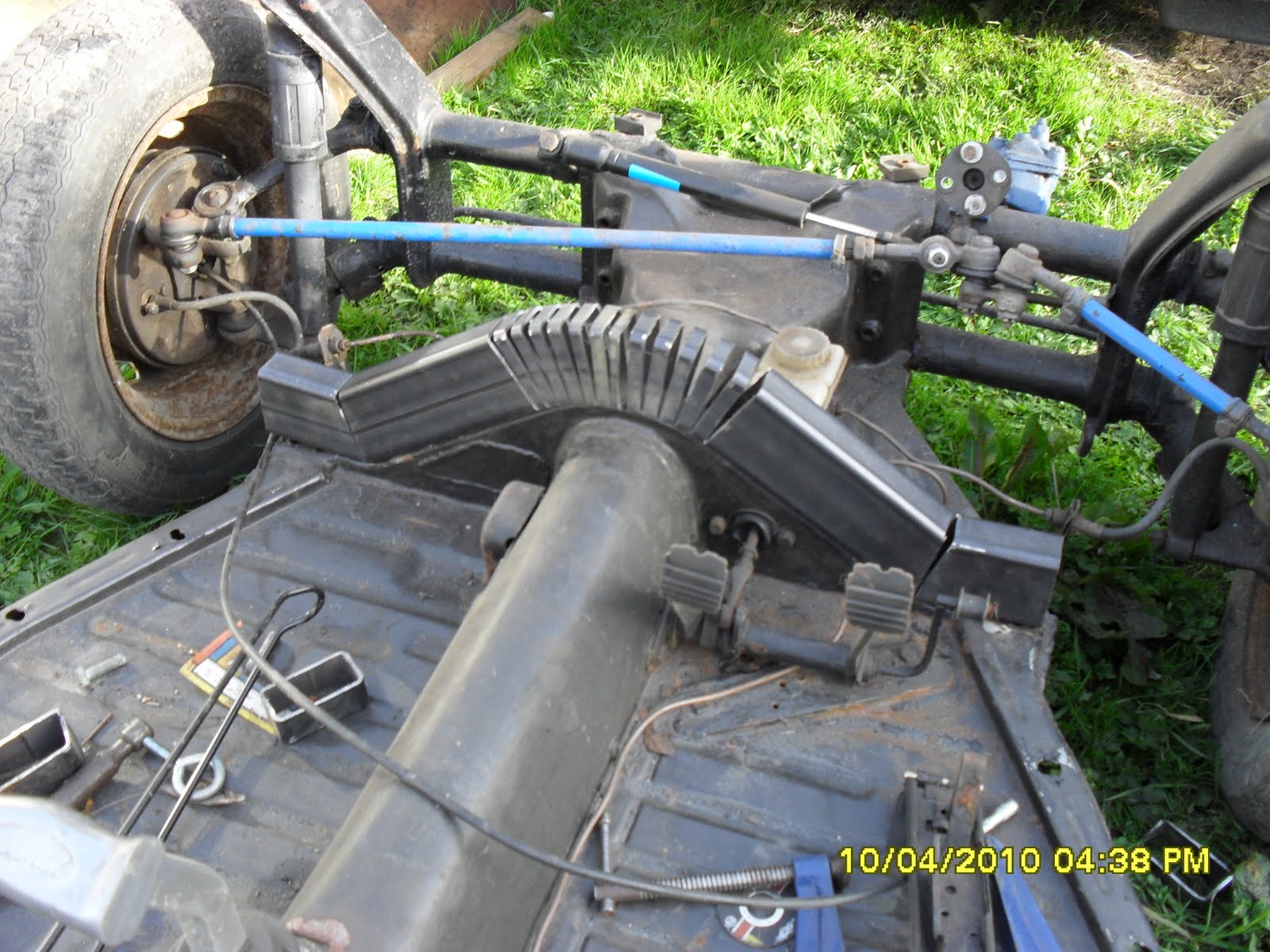
I started with the curve in the back section I made very small triangle pieces out of the box section to fill the area between the slits this held the position of the curve and allowed the weld to maintain it self . This was repeated until the whole curve was welded up. You can see from the picture the inner face was smooth as it required no welding whilst the outer surfaces would require grinding. the rear diagonals were all then fitted to the donor chassis and cramped in position so that the rear section could be welded. This proved quite successful I had cut a section out of each side to fit snugly into the rear chassis section. This was all tacked and welded. The middle curve section was then dropped in and the whole section was tacked and then welded up. I was very pleased with the result of this as this was a technically challenging part to make up as it had a lot of curves and bends in its construction. The rear section was then fully welded up and the whole rear section was retried on the rear of the chassis cross member. The next sections would again require cramping the new frame to the chassis. I welded up the curve of each of the front section so that it could check it on the chassis I used thin slivers of cut tubing in a wedge shape so as to not have to infill with so much weld. It was a pretty good fit. The front two halves could then be welded together whist cramped to the chassis. Once the two halves was welded together it was noticeable that one of the lower leg angles had moved due to the heat of the welding this angle was cut back out by using an angle grinder and the new angle was welded together again to make a good fit. The finished version was obviously incorrect as the top curve was totally wrong. I new this would not fit the chassis. I drew an initial template from the bottom of the section. When I superimposed it on the top It was noticeable that the curve needed to be at least another 1/2" higher. I stated fabricating a new top by making a new curve section that would fit the bottom. I made this extend further into the bend so that It would clear the existing welding. This was then welded up to make a solid curve. I was able to then position this on the top of the curve to allow me to mark the union of the two pieces this was quite complicated but surprisingly went very easy. You can see in the diagram left I have cut the two sections so that they mated seamlessly into the curve of the welded front section. The difference in the previous and the new curve is immediately noticeable. I tested this design on the body and chassis of a donor vehicle to my horror the whole top section was still wrong. Further analysis proved that there was a strange phenomenon happening. It appeared as if the sloping sections of the front section had to be thinner than the 80mm box to keep the same shape and profile as the bottom of the front piece. It looked on paper that these needed to be 12.3mm thinner. This was completely unbelievable. But yet with the top lowered 12.3mm the top would again fit the bottom of the section like it should. After a while scratching my head I decided the only reason for this had to be that the slopes vertical diagonal component had to be 80mm and this was the reason the width had to be reduced by 12.3mm. This was a very iimportant discovery as it meant the rear section may not be correct either. The math for this was also simpler than I thought it was basic trigonometry a jotting pad soon came up with the mathematics needed to find the new height required on the diagonal components based on the angle that the diagonal was leaving the vertical. Looking at the rear section this was also wrong and needed changing as clearly the end sections was wrong and not following the contour of the top either.

Front section finalized.
I new that I would have to lower the peek of the front section by 12.3 mm. To achieve this I would need to cut out this new section from the front all the way down to the flat ends. I would then have to remove 12.3mm and re weld the whole assembly back up . The picture right shows the top half lowered by 12.3 mm . This gives a vertical height in the middle of 80mm. Which is correct and now fits the body work perfectly. This would also need to be done for the rear section which is a much more complicated section. I would have to work again from the angle to the horizontal and use a trigonometry tan function to work out the new height. One really interesting thing about all of this is that the number of people that told me to get the tubing bent to make this would have all been wrong as this would not allow the body work to fit in the same way as my previous methods had not.

Rear Section finalized.
The rear section was with the new mathematical information also wrong the angle it raised from the horizontal was 20 degrees . Using trigonometry (80 mm/(cos 20) = 85.1 mm ) - 80 mm = 5.1mm shorter in the diagonal heights. It can bee seen from the photo left that the original rear section I had made fitted the bottom beautifully but the ends of the section where wrong and too short on the top section. This meant also the height of the tubing needed shortening by 5 mm. I started by marking out the cuts to each side diagonal and the increase in end required. With this I was able to cut the top of the diagonals and shorten the box tubing by 5mm. This also gave enough distance for the end pieces to be extended.

Two opposing side sections.
The side sections were much easier to fabricate to shape I cramped the side sections to the chassis and ensured they matched the curves in the chassis. I ensured that the lengths where longer than I required so that they could be trim to size. I cramped the rear section first and then moved forward placing new cramps to ensure the shape was correctly held in place. Some gaps where to large to weld so I used the cut out triangles from the rear section that I cut out and welded them into the larger gaps. This process yielded a much cleaner weld and it can be seen that it held the section together better. With this repeated for both sides the design was starting to come to shape. I tacked both sides so that they could be transported and welded up in a warmer environment. You can see with both sides cramped in situe the strength of this new section was already stiffening up the chassis. The picture left shows the two side sections tacked together before they were removed to be fully welded.

This was becoming a lot more complicated structure to build than I had figured I would need to cut the sections to shape and weld them up to make a complete chassis. This will be continued in the next episode.

Manufacturing a body lift kit - part two

10th April 2010
As I started to ponder the front and back sections of the body lift frame. I realized as I looked at the chassis that there was in fact more curves than I had originally seen when I appraised these sections. Specifically at the back I had tried to cut a section to fit the side rail by using a bevel gauge to find the angle. On revisiting the chassis it was evident that this was wrong as there was a very small angle 20 degrees at the end of the rear run sections that made the tubing hit it when it sat square along the chassis. Obviously this affected the way it was constructed. I cut the length of each diagonal on the rear of the chassis at 55mm which allowed a small overhang so that it could be trimmed when I had cut the curved top piece to make it fit flush for welding. I then measured 50 mm up each length and marked a center point to cut a triangle out to make the lower angle using trigonometry (tan 20) * 80 mm I worked out the base would need to be 28 mm. I measured and cut this triangle section out and bent the metal to form the correct angle . The curved section that sat around the access panel for the gear lever linkage was going to need to be created entirely on a curve. This would prove to be one of the most difficult pieces to get correct as there was no way to cramp it to the chassis to hold its shape like I had done with the other parts to weld them. The process of getting this curve took some time to get correct as it had to be accurate as the brake line ran directly behind it. I cut the back inspection plate curve at 20 mm intervals there was twenty cuts needed to form the semi circle curve. The rear section bottom angle was made by cutting one 30 mm piece out of the top edge of the box centered on 50 mm from the end of the tubing this gave enough material to be removed to create an angle of 20 degrees. The mitre between the diagonal upright and the curve section was very difficult to get to fit neatly luckily I had a very good friend John to help me and we eventually managed to get a reasonable fit. The front box section I decided was going to be needed to be constructed in two sections. The reason for this was it would be easier to construct two curves each side instead of four in one piece of box section. This allowed for the pieces to be cut and marked so achieving a good curve going over the tunnel that represented the original as much as possible. The lower angle approaching the tunnel was measured at 35 degrees using trigonometry (tan 35 degrees) * 80 mm I calculated that a triangle of 58 mm on the top base edge was required . I then cut slits at 10 mm intervals to allow the rest of the metal to be curved. The front two sections where then cut so the butted up to each other in the center. as you can see at this point the front and back sides had not been trimmed to length. I decided that the two curves front on back were stable enough to be welded off the car chassis. This was good as I wanted to get some experience of welding this material and in filling the gaps I had created with the slits. I knew I would need this as when I returned with the welded section sections I would have a large welding tacking job at hand. The picture right shows all the parts cut to shape. Some of the parts would need to be shortened after the sections front and back where joined together on the chassis. The reason for this was to try to ensure the parts hugged the chassis neatly. With everything cut I was waiting for a replacement welding helmet to turn up so that I could start welding. I was very pleased with the work and the help of my friend both with some of the difficult pieces and the use of his chassis to fabricate this lift kit onto. Whilst waiting for my welding helmet to arrive I noticed that the radius of the curves on the front cross section where different radius's top and bottom of the middle section. This would mean the front section would need the top of it to be remade to the same radius at the bottom. I decided this was something I could do once it was welded.


Manufacturing a body lift kit - part one

28th March 2010.

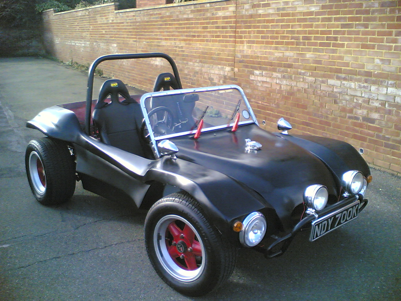
I had been searching the Internet for a body lift kit that would allow the body to be raised on my Buggy so that the pressure ducting from the turbo would fit under the rear of the body. I had originally considered that I would fiberglass the rear body area , but a good friend had suggested this as another option and it was then I realized it would solve two of my problems, the second being head room. I had really not wanted to change the look of the car to much and after looking at different hood designs I was aware that my head would go through a soft top with the current set up. I had thought that I would have to lower my floor pans to allow the seats to be placed lower than the chassis. This is a large amount of work and the body lift kit idea seemed to cater for both problems. I had found that in America I could buy a BugPack body lift kit. Pictured left. This seemed a little delicate for my off road requirements so I started to source some material to make the lift kit from.

I found a supplier ARC Fabrication Ltd in Hastings that supplied me with 80mm x 40xmm 3.1mm x 1.5m lengths this was ideal as I had been told that I needed four to go around the perimeter of the shortened chassis. I picked up the mild steel box section and started to ponder the best way of fitting it around the complex shape of the floor pan.

There was at least six curves to negotiate and luckily a good friend had a chassis that I could build the lift kit onto and was very helpful through the build process. I had put a thread on VZI asking which was the best way to curve the box section as I new there was several ways of achieving this. The consensus was that bending the material put stresses into the side walls of the material and that cutting and welding was a better option.

I decided I would have to see if there was a mathematical rule for calculating the number of cuts and the distance between the cuts to negotiate a curve. I had been told already that the curve on the leading edge of the chassis near the front needed six cuts that where spaced at 20mm intervals apart to negotiate this curve but had no idea how this had been calculated. This meant I needed to research this as I had to get over the tunnel and this was going to be very difficult without some maths to simplify it.

I started by working on the side rails. Initially these had looked like they only had one curve but in fact they had two on each side. I started by marking the rail were the curve started to come in at the front this gave me a position to start cutting into the rail. I marked the chassis were this mark intersected it so that it could be used as a reference marker to re-align the rail in the same position. I then marked out six cut marks 20mm along each rail, so that the 20mm intervals fell around where the curve was going to come. This gave me my cutting marks. Cut the box section using 1mm metal cutting disks these cut quickly tthrough heavy metal. It is very important to wear safety equipment with these cutting disks as they can easily cut through anything quickly. Three sides of the box section was cut so that it lost its rigidity and was able to be bent around the chassis to form an even curve.I used the 4" C-cramps to initially cramp the longest side onto the chassis. This gave a fixed point so that the the other half of the box section could be levered into position. I used a piece of wooden batten to pull each of the cuts out so making the distances regular and more easy to weld. The process was then repeated for the other side.

It was soon noticeable that the box section cut across the front edge of the floor pan. This didn't look very neat and I decided that if another curve going the opposite was was placed at the end it would bring the end of the box section back in line with the chassis. The angle of this curve was much tighter than the previous one and I decided to make six cuts at 15mm interval to allow for the tightness of the curve. You can see in the picture opposite that the box section now followed the perimeter of the chassis sides. I had only bought with me a few C-cramps and really did not have enough cramps to cramp both sides down hard. The result of this was that I new I would have to return and complete the front and back sections. I had decided to make the front sections out of two pieces and the rear section out of three pieces. The reason for this was to simplify the curves so that the box section would fit flusher with the chassis. I will return to make the front and rear sections in the next article.

Supplier
Arc Fabrication Ltd
Unit 1/2 Bulverhythe Works, Bulverhyth Road, St Leonards on Sea Tel 01424 715220

AS41 Magnesium Alloy Case Welding the tricks

23rd June 2009
The Magnesium/Aluminium case design of the AS41 case i renown for being one of the lightest design engine cases even by today's standards. This was the brilliant invention of the VW factories in Germany who originally built the engine to power planes. The downside of this design is that the Magnesium/Aluminium alloy was a mixture that was hard to weld. The obvious risk of this being igniting the Magnesium whilst welding so that the hole part you were welding burned with a large flash eating away its form. Traditionally welding these materials takes a great deal of experience as the welder needs to be aware of the composition and must apply only enough heat to weld and not combust. It is also paramount that you have a hammer with you available to beat the crap out of the area you are welding so as to knock the burning magnesium out of the area. The downside of this is that i can leave a larger hole than you start with. Crucial to the weld is also the composition of rod that you use and traditionally the flame is better controlled by a tig welder. Most people believe wrongly you need an Aluminium rod with a Magnesium content to weld the AS41 case. The result of this I found out quite quickly was not the answer and the shop that I asked to weld the case up produced the hole filled and taped but not surprisingly the plug they had welded in did not bond to the case and was simply able to be pulled out.

The correct welding rods to weld an AS41 case are in fact Magnesium rods with a low percentage of Aluminium. The actual percentage being 8% Aluminium to 92% Magnesium. These are available from Armour supplies Ltd in Hastings, East Sussex UK .

Withe the case welded so that the main gantry was plugged I was able to get the case re taped with the 3/8" NPT tap. I used a workshop for this and had to remove all the engine main studs so that it could be mounted in their mill. you can see from the photograph that I decided to have the area made bigger so that the thread had a good fetch into the casing.

The finished plug looks stronger and more durable than the original. I am very suprised this can be done and it blows a large rasberry in the faces of everyone that says it cannot be done or to put it a better way the people that have kept this a secret from us for a long time are now all aware we all know,. I look forward to seeing a lot more cases re welded in the future.

As the answer is a vertible YES!!!!!!!!!!!!!!!!!!!!

A new 1300 dual port engine

5th June 2009
I had started to realise that with the break up of my relationship that my new 2L engine was going to be something further distant that I had planned. I was planning to have the engine in by the end of this year and with the custody fight and various other depressing events I needed to find a solution that would get the engine situation resolved as my friend had been very good to lend me his engine lump but obvuously I wanted this resolved. I managed to purchase a 1300 dual port lump that had been dry stored in a lockup for some years. Although the engine had some end float outside the allowed parameters generally it looked in good condition.

Initially I decided that the engine would need stripping and the piston rings would need replacing , but I also found that the con rod bearings and crank bearings really could do with renewing. I really had not planned for this and had decided against renewing at this time until i was placing the pistons back on to the case and pung one of the pison ring clps accidentally into the casing.

This normally would have been a disaster but to be honest I was already considering stripping the block down and decided that this was now had to happen. You can see from the diagram that the gudeon pin clip was lodged beneath the camshaft and was totally uneccessable from the oil plate. I took out the crank hsaft and camshaft and cleaned the engine parts thourougly with gink and then jet washed them off to remove any final engine residue.

The engine casing parts cleaned up fairly well and without the use of a dishwasher I was unable to get them as clean as I had with the other cases I had worked on. I couls ssee from the bearing journals that the crank had not damaged the casing and the case was in good condition. I decided whilst I had the case apart that I would full flow the oil system so that it would be able to cope with any future upgrades. This consisted off tapping the casing outlet of the oil pump for a 1/8" NPT thread and tapping the main oil gantry to provide a return a 3/8"NPT thread. The oil pump casing was quite easy to tap and this can only be done with the negin in half. The 3/8"NPT main return thread was a hole differant ball game. The thread would not take in the casing and instead just powdered up and dug a hole . This was a disaster as there was not much room in the casing to put in a case saver. I new that I would have to delve into the world of case welding something believed to be a Pyrotechnics black art.