Search This Blog

Showing posts with label Battery Box. Show all posts

Fitted a new Battery as the old battery

2nd March 2013
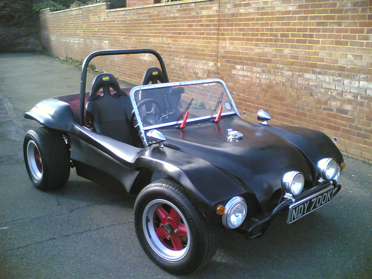
This year as normal I am replacing my battery in my buggy. I have been doing this regularly as I am finding that not using the buggy for half the year and running the alarm on the buggy has had its toll on batteries. The new battery I fitted had a slightly bigger handle as it was an Exide. This caused an issue with the bolts on the connectors meaning the battery box lid would not fit. I was intending to cut these down but found to bolts from a pair of skate wheels that fitted flush and removed the problem totally . The new battery allowed the engine to fire straight up.


The engine started well . I was quite pleased about this as last year I had to replace the ignition lead set. I took the buggy out for a run down to the beach. It was a gorgeous sunny day.

Making a battery box cover

22nd April 2012
Last week I successfully relocated my battery so that it sat in the middle of the rear seat panel.

I knew that the battery was just lower than the edge of the box I had created and had intentionally made it this way so a lid or cover could be attached over the battery securing it  from fingers that may be on the back seat.

I started designing the lid by measuring the aperture in the top of the box. When I created the box I had noted that the two corners that I had used that was already joined flared  out slightly and had made my two new corners to look the same. This meant I had to measure the inside area allowing for a 2mm tolerance. You can see in the diagram to the right the sizes marked up. Once I had my measurements I made a paper template this size and put it through a plastic envelope heat sealer to make it plasticized. I found a piece of flat Stainless a tea tray and laid this on the surface so that I would be able to put the fibreglass on top and gauge the size I needed. I layered up four sheets of fibreglass with fibreglass resin  this took longer than normal to set because of the weather so I used a paraffin heater to raise the temperature in my workshop.

The matting I applied was just larger than my paper pattern that sat in the A4 plastic heated liner. This is the same machine that does plastic badges. This stopped the fibreglass sheet sticking to the tray. I left this over a day to dry and cure. Once hard the fibreglass was turned over to expose the pattern on the other side. I used an angle grinder to cut through the plastic and fibreglass around the edges of the template pattern so that the sides were clean cut and crisp.


I then removed the template which peeled of leaving a smooth surface The fibreglass panel was then sanded on the opposing side until the thickness of the fibreglass was consistent all over the panel. Once the panel was smooth I painted the rougher side with black Hammerite hammered paint. This sealed the surface on one side. So that I could concentrate on the other. I used Car under seal to spay the other side leaving a rippled effect . This was the same process I had used inside the car.

The underseal surface dried quite quickly leaving a slightly textured surface. This need no further preparation and I was able to spray m 1k black paint onto the surface . This sealed the under seal and fibreglass . I knew I had run out of thinners and would have to buy some more . I wanted to finish the panel and decided to try making up the 2k Lacquer and hardener and adding the gold leaf with a view to using a large brush to apply it.

 The finished lacquered panel looked amazing and you really could not tell it had not been sprayed  with a spray gun. The panel was then checked for size and it fitted neatly into the top of the box. I had purchased some stainless fixings to secure the top from a boat chandler I offered these onto the lid so that I could gauge how they looked against the finished surface. They fitted in four places and I was able to decide were they would fit.


I attached the eccentric / pull over fastener to the panel with M5 countersunk bolts I used these as I did not want them to interfere with the battery and to be pulled in flush to the fibreglass. Once these were all bolted in place I offered the panel up to the box and marked the positions of the stainless box to locate the eccentric keeps. I fixed theses to the rear of the box through my body bar . I used self tapping screw's to fix the front eccentric keeps.

The lid was latched in place and sat neatly over the battery . The eccentric / pull over  latches had little loops on them that either a wire and a single padlock could be used or four separate padlocks could also be used to secure the battery from theft. I was very pleased with this as it made the rear seat area a much safer place to be. I was also wondering whether I could build a seat to go on this new area.


Moving Battery to a Battery Box

12 April 2012

Two weeks ago I replaced all my convertible roof studs but two as I needed to get longer bolts that i could tap out. Unfortunately the latest revisions came out for the 2012 UK MOT a condensed two page document that has created work for all V.W owners. My existing battery location became foul to these regulations as it was not totally secure and was not covered.

Having seen buggies with a recessed battery box in the back seat where the back seat was a long bench, I decided that it would be interesting if I could recess my battery into the rear seat area and release the space that the battery had previously occupied. I started looking for large pieces of stainless sheet .
I  measured my battery  which was 205mm x 175mm x 175.  I made a paper stencil to check the size of a box dimensions which would contain the battery and allow for the battery to be secured and the wiring to all fit . The dimensions of the box top I arrived at was 230mm x 190 . The template I made was very useful as it allowed me to place the template on the rear parcel area and check that it would fit. I had already decided that I really wanted the battery in the middle of the seat and was pleased that it appeared as if  I had enough room to fit the battery here.

I discussed this position with a friend Jon as I quickly realised that it would quite successfully free up two passenger seats. The outcome of this discussion was the question was whether the box would hit the gearbox. I measured the distance between my highest point on my gearbox near the new battery location and this was 190mm . Luckily my 80mm lift kit had given me the extra height I needed. I quickly worked out by drawing a flat layout of the box that I would need a piece of stainless steel minimum 1m x 400mm . I checked various metal stock companies and realised that the cheapest i could find this was on eBay at some £69.00 GDP. Clearly this was too expensivet and I would have to source the Stainless Steel from a different source.

Fortunately the solution was not to far away. For several years I had been storing my Welding spares in this stainless Steel tin . It was made from 1.2mm Stainless and looked quite adequate in size to be cut down . I started marking out the two opposing corners one with a floor and the other without . I used pencil to mark the outline and cut the two sections out with a 1mm angle grinder blade. The resulting parts were then chased along the edges to debur any sharp edges. The two parts were then assembled to see how they would fit together.


The resulting box was not bad and the two pieces fitted well clicking together to form a strong small box. I decided that I would have to bend the top mounting plates over . I used two pieces of right angle iron in a vice to clamp the stainless sheet along the line i had drawn to indicate the fold. I then struck the stainless steel with a rubber mallet to bend and fold the stainless along the angle iron at a right angle to the two irons in the vice. I repeated this for all four of the sides.

 I took the two box sections to Fullers Steel fabrication to have the two parts TIG welded. The resulting box was strong and gave me the dimensions that I made a template up from . This I stuck the the back centre parcel shelf of the buggy with tape . I used a Starret hole cutter to cut out the corners and used an Angle Grinder to cut between the four holes . This made a hole in the rear seat area directly over the  gearbox.  I drilled some holes in the box supports and made a rubber seal from an old rubber mat. The box dropped into position.  I used a rubber mallet to bend the sides to fit the profile of the seat and cut the front down to sit flush on the front of the rear seat area. The battery was then placed in situ and the new battery placement could be seen for the first time.

I enclosed the battery in the old fabric cover and connected up the battery connecters and went out for a short run in the beach buggy to see if the gearbox knocked the box out of its position. My route I chose was a very bumpy one that I knew would make the suspension work hard. The trip took about 25 minutes and I was soon back in the garage happy as the box had remained in position. I looked underneath and had a good 25mm clearance


between the box and the gearbox. I removed the battery and old cover and knocked the box out of the hole. I cut two holes in the top back section of the box for the new routed cables to come through . I then fitted these with grommets another UK MOT 2012 item which seemed very obvious. I removed the old earth wiring from the chassis bolt and threaded the positive supply from the alternator out of the chassis and back into the battery box. I shortened this and fed the earth wire alongside it. The wiring had now all been removed from the back seat area and with the old battery mount removed I was able to see for the first time how the new seat areas would look.

I mounted the battery in the box and reconnected the new supply lines . It was immediately noticeable how much new space I had created on the rear seat area. I started to think about seating types and even new speaker placement positions that had also been created. I knew I had to secure the box and I also had to secure the battery to the box and create a lid to enclose the battery from the elements I was in two minds what to make this out of. I liked the shiny stainless but also felt fiberglass would look fantastic as it would match the car paint. I was very pleased with the new position and was beginning to wonder why I had never seen this done before as it looked so natural. The box was secured in position with some cut down flush Allen bolts .

I made up a stainless right angle battery holder that was the same size as my battery box I drilled two holes in each end 10mm and used two 10mm eye bolts that I purchased. I cut two holes in the box side walls to allow the eye bolts to go through . I cut one side away from the bolts to make a hook. I used this to secure the battery into the battery tray. The bolts and angle bracket fitted neatly onto the shoulder of the battery. I bolted the battery box in position and went for a run . I decided that I would try going for a longer run than I usually do. and set off to the town of battle some 20mins away. I soon found that the car ran better after it had a sudden  boost on the open road. I returned to the garage happy that there must have been a blockage in the carburetors. I still however had not got the buggy over 60mph and was wondering if it would make faster speeds I also happily noted that the speedometer was accurate at 40mph & 60 mph.


Battery, No reason for not starting

13th January 2012

The troublesome Friday 13th had arrived for some but this year I was given a lovely surprise and thus has become a lucky day for me for different reasons and is certainly one i will be noting in my diary.

Since my new year visit to my garage I had been experiencing problems with my battery not providing enough power to start the car and turn over the engine . I had wondered if this was because of the high compression with the new 1641 Barrels and Pistons. However in these austerity times, needs meant I had to locate a battery from a different source I had not realized although I had bought a higher amps battery that although it was a 60 amp battery it only had 335 amps of starting current( As seen in the picture above.). I was researching higher Capacity batteries and discovered quite by accident that most VW Beetle batteries where rated at 420 amp starting current or even 440amp. This clearly was the problem as I had more resistance due to higher Psi in my heads and a weaker starting capacity.

I rang my local dealer and he told me the Bosh 63 batter was rated at 44 amps with a starting current of 440amps . I would have to buy a different battery to solve this.

I also turned the buggy round in the garage so I could get better access to the engine.

Rear Body Modification

12th March 2008
After the first attempt at installing the IRS brackets I realized that the rear body dropped quite low into the area where the new IRS A-Arms where going to fit. I had already cut down the drivers side battery box and removed the side of the frame horn ready to use the IRS bracket jig. I had been thinking about the frame horn trusses and new that they needed to fit between the upper shock absorber mounts in addition to needing to create space for the passenger side A-arm to move. The spare tyre well placed a bulge on the underside of the body that was directly in the way of any bar that would traverse the top shock absorber mounts. I was already committed to rebuilding the battery box bottom and decided that whilst I had access to the rear of the car that I would cut out portions of the spare tyre well laving enough space for the new IRS parts and the frame horn truss to fit. You can see from the two images above the differences in the bottom profile of the buggy. The height of the rear projections in to the chassis had been reduced substantially.

The picture to the right shows the inside view from the rear seat area. You can clearly see that the cut-outs follow the line of the battery box. With the areas rebuilt and the rear shelf extended to meet the new back of the spare tyre well area. This hopefully would leave enough clearance for the frame horn truss to be fitted, if and when I managed to find one for sale at a reasonable price.

Finally I was nearly ready to see if the new gearbox fitted.

Installing the IRS A-frame brackets - part one

11th March 2008
The fabrication of the Jig for locating the position of the IRS A-Frame brackets was not something I needed to do as I found a seller on www.volkszone.co.uk , who was wanting to sell the jig he had for building his own IRS. I picked up the jig from him and was soon aware that he had not used the conventional bolts that bolted the A-Frame in to position the brackets. The tubes that ran inside the brackets was only the size of a 1/2" UNC x 4" bolt. This did not give a steady position for the brackets and I decided that before using them I would have to check them against a real IRS chassis to ensure that they gave the correct position in practice. This would not be a problem as I new the location of a 1302s chassis that was bare at a friends workshop.

I decided that I would not be able to fully position the brackets, but decided to clean up the frame horns and remove the surplus material along where the bracket would sit. Once I had the jig problems resolved I would be able to cut into the frame horn to get the final position of the bracket.

I started with the off side of the car removing the brake hydraulic lines that where still left. It was pretty clear at this point that my battery box was to low to gain access to the bracket position. I was also worried that being so low the A-arm would hit the bottom of the box as the suspension moved. This was not going to be an easy process with the body attached to the car, but I decided it looked feasible. I started by drilling a hole in the fibre glass that I could push the blade of a jig saw through. This allowed be to cut along the back and the inside of the battery box several inches from its bottom. I then managed to use an angle grinder to cut from the inside of the box the outside edge of the battery box. The angle grinder was also able to cut the box around the torsion bar, which enabled the bottom of the box to be removed.

With the bottom of the battery box removed I had access to the flange that ran along the outside of the off-side frame horn. I started to cut the metal with the angle grinder and cutting disk alongside the handbrake cable. I was able to cut the material back all the way to the torsion tube. When I had finished cutting this area out I switched to a grinding blade and cleaned the of the paint. I knew I would have to build a new floor to the battery box at a later date but I was pleased with the progress I had made with the drivers side.

The weather forecast for the next few days was awful and I was not able to get into the garage to cut the other side down. I had decided I wanted to cut the fibreglass on the nearside of the car , which was rumoured to be for a spare wheel. This was ludicrous of course as there was no way a beach buggy wheel would fit in this space. The main reason for removing this area was to allow for the future placement of a German Kafer Cup type Torque Bar Kit. As seen on the left. The design of this needed to allow a bar to cut straight across the spare tyre well and under the rear seat rear of the buggy. Currently this was an expensive piece of kit and I wanted to see if I could build in space for it to fit should I be able to get hold of one or build one.

The weather was suspected to get worse so this was all put on hold for better weather conditions that where more favourable as the high winds had nearly took the garage door off already.

Body Alteration part one.

A week later.
With the wooden blocks screwed in place i could gauge the profile that i needed to make to fit this section onto the chassis. Several trial fits of the tub onto the chassis had been made to check that the tub fitted evenly on the chassis base.

I made cardboard templates of the profile that could be used to check the height of the build up of fibreglass. I intended to use a vernier type gauge to ensure that the build up of fibreglass matched the distances that I could measure on the cardboard profile this giving me an accurate indicator. The reason for this process was that laying down fibreglass over a large area meant that long lengths of fibreglass sheeting needed and the wooden blocks had to be removed before any fibreglass could be laid.

The wooden blocks were removed and the surface was cleaned up with the 160 grit sanding angle grinder disk. After final preparation with the cellulose thinners. I was able to start fibre glassing. It was soon clear that my guess at the amount of fibreglass was sadly under estimated.

A week later and with Ben now turning up regularly to help with mixing of resin material the transom was building up slowly. I had not anticipated that the fibre glassing would over spill the area. This amazingly was a helpful thing, it gave strength to the new material as it was talking on the contour of the body work and by encroaching forward past the transom it meant I could cut back the material to provide a clean profile in the inside of the tub. The benefit of this was that I could ensure the integrity of the fibre glassing was good. The picture on the right shows the material cut back. I found that an angle grinder was the only way the material could be cut it was amazingly hard. I estimated the amount of fibreglass used at £300.00 which meant in reality buying a second hand shell was more expensive to build as a restoration than buying a new one. This was not something that did not bother me as by then I had found out that FibreFab had stopped making the SWB Rat and where no longer in the United Kingdom in Wokingham. I was restoring a classic beach buggy that there were few examples off left running. Additionally I drew energy from my fathers illness I now had a mission: " To take my father for a ride in the car that we started building together more than 20 years previously".