 10th April 2010
As I started to ponder the front and back sections of the body lift frame. I realized as I looked at the chassis that there was in fact more curves than I had originally seen when I appraised these sections. Specifically at the back I had tried to cut a section to fit the side rail by using a bevel gauge to find the angle. On revisiting the chassis it was evident that this was wrong as there was a very small angle 20 degrees at the end of the rear run sections that made the tubin
 g hit it when it sat square along the chassis. Obviously this affected the way it was constructed. I cut the length of each diagonal on the rear of the chassis at 55mm which allowed a small overhang so that it could be trimmed when I had cut the curved top piece to make it fit flush for welding. I then measured 50 mm up each length and marked a center point to cut a triangle out to make the lower angle using trigonometry (tan 20) * 80 mm I worked out the base would need to be 28 mm. I measured and cut this triangle section out and bent the metal to form the correct angle . The curved section that sat around the access panel for the gear lever linkage was going to need to be created entirely on a curve. This would prove to be one of the most difficult pieces to get correct as there was no way to cramp it to the chassis to hold its shape like I had done with the other parts to weld them
 . The process of getting this curve took some time to get correct as it had to be accurate as the brake line ran directly behind it. I cut the back inspection plate curve at 20 mm intervals there was twenty cuts needed to form the semi circle curve. The rear section bottom angle was made by cutting one 30 mm piece out of the top edge of the box centered on 50 mm from the end of the tubing this gave enough material to be removed to create an angle of 20 degrees.
 The mitre between the diagonal upright and the curve section was very difficult to get to fit neatly luckily I had a very good friend John to help me and we eventually managed to get a reasonable fit. The front box section I decided was going to be needed to be constructed in two sections. The reason for this was it would be easier to construct two curves each side instead of four in one piece of box section. This allowed for the pieces to be cut and marked so achieving a good curve going over the tunnel that represented the original as much as possible. The lower angle approaching the tunnel was measured at 35 degrees using trigonometry (tan 35 degrees) * 80 mm I calculated that a triangle of 58 mm on the top base edge was required . I then cut slits at 1
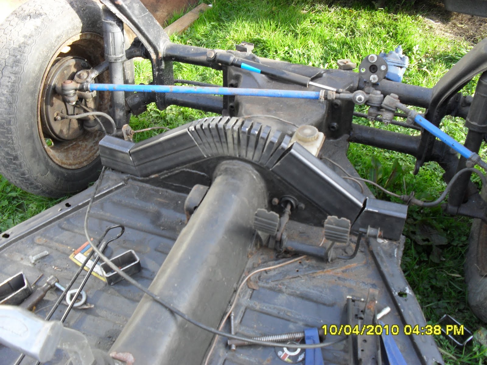 0 mm intervals to allow the rest of the metal to be curved. The front two sections where then cut so the butted up to each other in the center. as you can see at this point the front and back sides had not been trimmed to length. I decided that the two curves front on back were stable enou
 gh to be welded off the car chassis. This was good as I wanted to get some experience of welding this material and in filling the gaps I had created with the slits. I knew I would need this as when I returned with the welded section sections I would have a large welding tacking job at hand. The picture right shows all the parts cut to shape. Some of the parts would need to be shortened after the sections front and back where joined together on the chassis. The reason for this was to try to ensure the parts hugged the chassis neatly. With everything cut I was waiting for a replacement welding helmet to turn up so that I could start welding. I was very pleased with the work and the help of my friend both with some of the difficult pieces and the use of his chassis to fabricate this lift kit onto. Whilst waiting for my welding helmet to arrive I noticed that the radius of the curves on the front cross section where different radius's top and bottom of the middle section. This would mean the front section would need the top of it to be remade to the same radius at the bottom. I decided this was something I could do once it was welded.







 Posts
Posts


