Search This Blog

Showing posts with label Engine Removal. Show all posts

New Year 2011 Strip down

2nd January 2011
My New Year started with a vengeance to find the problems that had riddled my project for six months previous thanks to a great deal of motivation supplied from a very good friend and fellow enthusiast. We decided to first of all remove the engine which had been rebuilt some months before and which had seized in the garage as it had been left for too long without engine Oil. The process I had tried to re free the engine had obviously had a toll on the clutch and clutch plate. The pictures show the power that had been worn off the clutch friction plate.

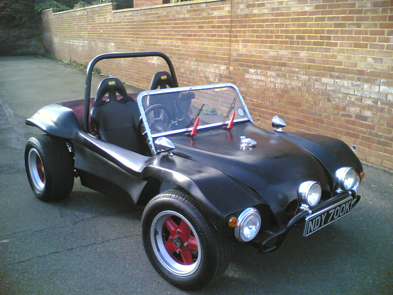
Once the engine was out we decided that as time was available we would strip the Beach buggy right down to its chassis, in an attempt to see if the body lift kit would fit onto the buggy chassis as it had been previously fabricated on a donor chassis.

The strip down was fairly quick and everything seemed to come apart really easily. I put this down to the quality bolts I had used.

First the seats were removed by undoing the four bolts that went through the floor pan. Once the two seats were removed, it was then possible to get to all of the 8mm perimeter bolts that hold the body work to the chassis. As several of these hold in the Roll Bar these were removed also and the Roll Bar was lifted out. The windscreen and bonnet then had to be removed along with the petrol tank.The next problem to get over needed the front lights and indicator wiring to be removed from the Fuse box. Additionally the ignition wiring harness and the brake light and horn wiring all had to be disconnected. The front body mounts could be then removed allowing the body to be lifted off. The body lift kit could then be placed on the chassis to see if it would fit. Fortunately it did the work I had done in the summer was fruitful and the two mated perfectly. With the body lift kit on, the body work was placed back on to see how the ride height looked. The front definitely needed to have the adjustable beam that I had been rebuilding and I felt this would bring the front down so that the front wheels filled the wheel arches once more. The front seats were placed back into the car temporarily so that the seat height could be checked . The raised height was fantastic just what I needed so that a soft top could be fabricated that would not need a head hole for my head to poke through. A shopping list was then made to acquire longer bolts some and a new 9mm drill so that the body work could be fixed back onto the chassis. As I had taken the body work off I felt that it was in need of a clean up and thought it would be a good idea to fibre glass the areas properly from the underneath where I had cut out the areas for the cross bracing in the rear.

With the bodywork back on it was apparent that the Roll Bar would be very much higher than it needed to be. We found that it would just fit snugly inside the body lift kit. This would allow it to retain its height and could be bolted through the the Roll Bar and the side of the Body Lift frame. This had the advantage of making a strong structure that contained the people sitting in the beach buggy.

It would be some time before the car was back in one piece again.

A new start and a true friendship

13th August 2008
"When things get bad and you wonder what on earth you are doing . Sometimes a saint appears and gives you a differant solution....!"

With my crankcase cracked and my engine re-build put on hold. I was lucky enough to have a good friend step out and offer me a tempory solution. My friend John knowing my dilema offered me one of his engines to put in my car until I had researched and purchased the parts I needed to build a new engine that I had propossed to do. This was a gladly accepted gift as I could test out the disk conversion and IRS conversion that I had been working on for the past few months. Obviously without this engine It would be some time before I could have the new engine built up and runnning in the car.

I needed to use the clutch and cover plate from my old engine along with my distributor, HT leads and rocker arms. The engine was fitted into my buggy in an afternoon.

With the engine fitted I new I would have to redesign the number plate fixing. I had previously wanted this to look good and to be made out of stainless steel , but as the buggy previously had a rear cage that still needed to be extended I felt it was a good time to redesign and make the mount i really wanted. The number plate body was made out of 5mm stainless. The holes where cut to help reduce the weight of the piece I made a mount that would take my existing stainless steel tube number plate lamp. The finished result looked very good and I was happy that I could still fabricate it after the problems I had had with the previous engine.

I had also been lucky enough to find a new crankcase on vzi and although it was a little expensive I was awaiting some photos.

Engine Overhaul - The break down

25th July 2008
Readers of this blog are aware that I had a catastrophe that was caused by a small piece of bakerlite that sat under the fuel pump. Whilst servicing a crack in this item I managed to shear of the Bakelite and drop a small piece of it into the crankcase. This was disastrous as my engine had done less than 250 miles since its last rebuild and there was no way of retrieving it other than dismantling the engine. Firstly I must say a thanks to the informed members of VZI who stated not only where the parts would end up but where they would get mashed and what they would destroy if left in situe. To be quite frank they stated the exact position. The yellow arrow points to where the bits ended up. This is just under the timing gear on the camshaft. The green arrow shows the oil feed to the crankshaft. The red arrow shows the lower pump ring that the Bakelite pump bush fits into.

To be honest I am glad VZI exists. First drain the engine oil.

I stripped the engine down in a day removing the cylinder heads by removing the rocker covers , then the rocker shafts and then the eight nuts that hold each of the heads in place. With the heads removed the barrels could be removed taking special care to get them out so far that the gudgeon pins could be removed and the pistons removed still attached to the barrels. This is a little tricky but with a pair of long nose pliers to remove the circlips the pistons can be removed by sliding out the gudgeon pins. These can sometimes be a little stiff and a warm air blower like a paint stripper is enough to gently warm the piston to make the pin slide out again. With the pistons and barrels removed the main pulley can be undone at the front of the engine. If this is tight then the flywheel will need to be locked in position. Personally I tried to use a bar between two bolts and still resorted to buying the correct tool from eBay. This fits into the top engine bolt and securely holds the flywheel so that the front pulley and then flywheel nut can be undone. The short block is then able to be split. I removed the cylinder studs and the oil pump and the oil strainer first to allow better access to the case. There are eight large 17mm bolts and a large number of 13mm bolts around the case that all need to be undone. Make sure that you have got to all the 13mm bolts as there are some that are hidden tight against the back of the fly wheel and also in other hard to get to areas. With all the engine nuts undone . The case will still be stuck together. You will need a rubber mallet or a piece of wood and a hammer to carefully knock the case apart generally speaking its easier to lay the engine on a block of wood on its left hand side so the eight large studs are facing you. There are several good places around the case that you can hit , which will break the case seal. Once you have the case halves separated you can draw the top half on the engine case of the bottom. This will expose all of the internal workings of the engine so make sure you have a large quantity of rags or cloths that you can mop up the oil slick that comes out. Before going further you need to retrieve the cam followers that have fallen into the bottom case. You also need to check that you have two dots on the crankshaft camshaft timing gear and one on the camshaft gear. these are vital to lining up the engine timing, when the hole engine is put back together. Once this has been determined remove the camshaft and cam bearings and place them in a box. Carefully lift out the crankshaft with the con rods and put this in another box with some rags to soak up the oil. You need to ensure that you have all of the bearing halves out of the engine.

With the cases bare you can start to mop out the engine oil. It is generally better to get your case professionally cleaned if you can locate someone who will do it for you.

I have purchased a new Bugpac camshaft and a barrel and piston Marle forged set-up that will bring the engine CC to 1914cc when they are fitted. I will need to acquire a new set of heads before I can have the case altered to fit them. These are very expensive and I will have to work out which ones re the best to use for their respective cost.

Next I will remove the oil plugs and re-thread them to allow for any eventuality that the engine needs in the future. I ordered the brass screw caps 3 x 3/8 NPT , 2 x 1/4NPT , 5 x 1/8th online from http://www.airlink-compressors.co.uk/Fittings/plugs.htm, unfortunatly thier website ordering was down and I had to telephone the order through. In the mean time I had to find a 9/16 drill bit and a 1/32 or American R size drill. I choose the 11/32 as I already had one. The next challange was to locate the taps. My tap set came with a 1/8NPT trap but finding a 1/4NPT or never mind a 3/8" NPT tap was going to be a challange. I posted a wanted advert on VZI to see if anyone had any.

I started cutting the threads for the 1/8NPT this seemed fairly straight forward. I had to shorten the tap I was using to allow me to get the thread further into the crank case. I fitted the brass plugs into the threads as I went. I then retrurned to them to remove them finding one had stuck tight. Foolishly I tried to remove the plug after the allen key slot rounded in the plug. I used a screw puller and to my horror cracked the crankcase around the gantry
Was this the end for the crankcase would I need to buy a new engine?

Engine removal

1st March 2008
It was a sunny day and I had started the afternoon by removing the distributor drive shaft and the alternator and pedestal to see if there was any way I could see into the engine and spot the pump debris. This was soon written off as a bad idea as the access was restricted.

I started removing the wiring to the coil , the distributor and the alternator. I removed the fuel line and started on the three nuts and one bolt that held on the engine. These came undone fairly easily and with the help of a good friend and a jack was able to get the engine out and onto the floor. We moved the engine to the side of the garage and I took look at the transmission.

The first observation's showed that where I had rebuilt the battery compartment and the tyre well the new IRS components would hit the underside of the body, this was annoying as it was obvious that the body work was probably fitted to an IRS chassis before my changes. I would have to cut the body work back to allow room for the new A-Arms to rise up to the bump stops. I also noticed that my alternator B+ line had scorch mark in it and it looked like it had been sitting on the exhaust.

I would have to put axle stands under the rear frame horns and jack up the rear of the car to raise the rear wheels of the ground. This would allow me access to the gearbox and allow me to remove the rear wheels and gearbox assembly.