29th June 2011
With my engine refitted to my buggy I was getting close to MOT time.
My first problem I noticed was that the FUEL pressure was two high and I needed a regulator to bring this pressure down to the 3.5psi that my carburetors would run on. This should have been a straight forward exercise but to be honest took a lot longer to acquire than I thought. My first purchase did not turn up and the seller refunded my payment the second pump turned up and it was a high pressure Malpasso pump that would not provide a low enough flow rate. I decided to keep this as I felt my 2L engine I had in bits would benefit from this. Finally I decided to buy a new regulator from VW Heritage as i felt this was the only way that I would solve this issue. I kicked my self as I sold my last regulator and vowed not to sell this one. With the regulator fitted my engine ran up and ticked over quite well if a bit rough. I decided to get some more fuel and return to adjust the clutch which was a little high . I tried restarting the car after this and the fuel pump would not run!
Having decided that the mechanical pump baker lite bearing was not going near my car again after fishing bits out of my case twice I had fitted an electric pump a Facet POSI-FLO EFP-3 I name and shame it here as it failed even before the car made it on the road. I cannot believe the reliability of this pump and have now had to purchase a new pump which again with some trepidation is a Facet also. The Facet Silver top pump is made out of metal and seems to relieve better reliability reports in message areas on the Internet . I only wish I had researched this first pump choice better. I hoped it would be more reliable.
I was hoping the new pump would turn up in a few days. I also have been told that this pump needs to be mounted vertically with the filter at the bottom as this is the manufactures suggestion. S next time I will be making a stainless bracket to do this.
Making a reinforcement rear body support bar
25th June 2011.
Having managed to get my front bumper to fit I decided that in the light of my fuel regulator not turning up I would have to finally get round to building a new rear body support. This would be version two as the previous rear support although strong interfered with the position of my exhaust and I had to remove it . I decided that I would try to make the new support so that it could use one of the existing chassis mounts. I choose the mount nearest the shock absorber mount as this was quite near the body work and had a clean flat position near the body work. I bought some 40mm X 8mm stock mild steel 4m which I had cut into 1m 1.5m and 1.5m so that I could get them home from the steel suppliers. This was similar material I had successfully used on the front bar.
I started fabricating the bracket by measuring the distance from the bracket to the body work. This enabled me to make a piece up that would reach onto the body. I welded another piece onto this at right angle so that it would come out from the bracket and run flush. I placed this on the body work and measured the mounting hole coming through the chassis. This fixing was a M10 fixing so I drilled a 1.5mm hole in the bar. This could then be bolted onto the mount. I then used a different piece of bar held horizontal to work out the height that i wanted the bracket to be on the body. I welded this on and made another bracket mirroring the first. I tried to bolt this on but found that the body work was concave and not flat and therefore the body was sitting away from the bracket by some 25mm. I would need to bend the bar to make it follow the shape of the body work. This turned out to be more simple yet more involved than I anticipated. I first of all tried to heat up the bar, this could not get the bar hot enough to even start a bend. I eventually found three 22mm tubes and used two of them one side of the bar and one the other against the metal in a vice. The vice could be then be tightened to bend the metal work. I put three of these bends into the bar and repeated this on the other bracket. With the side brackets made I bolted them onto the car and measured the width of the body work to create a join between the two side brackets i measured this as 94cm and welded a bar on. I also added some small tabs to the side bars so that I could add an under seat support bar. I then tried to refit the bracket and to my dismay found that even with the 80 mm body lift kit there was not enough room to get the bar in without removing the engine. I decided the only option was to cut the bracket in half and lap another piece of 40mm x 150mm to splice the two pieces with bolts. I welded this to one half of the bracket and drilled the other half whilst the bar was still together before cutting it through one side. The resulting two bars then were fitted to the body work the bracket had to be pulled into the body work to allow the two bars to meet. The next problem to overcome was how to drill the body work behind the fan housing to get the bolts through the bracket and fibre-glass. I found that I could heat up a small wood working bradel and use this hot to push through the bar into the the fibre-glass marking the position of the hole as this would push tight through. I could then frill the holes from the inside of the body work. With the brackets mounted I started to fabricate the cross bar . This was made by measuring the distance between the two drop down brackets a length of 935mm bar was cut and some 90 degree up-stands welded on each end. This was then drilled so that it could be bolted to the tabs. I then took the brackets of and painted them with Acrylic black paint before refitting them to the car.
Whilst I was making this bracket I also found some Stainless steel and made a bracket for my front number plate. I made this is in a similar construction to my rear plate. I used an angle grinder to cut the perimeter after drawing around my number plate. I then drew diagonals onto the square plate so that I could drill the corners of the intersections. This meant I could then use the Angle grinder to cut out the inner triangles from the plate making it lighter. I then bent a piece of stainless steel 10" long x 4" this was then bolted onto the number plate backing and protruded enough over the bumper to allow two bolts to be used to bolt it securely on. The finished plate was then cleaned and thick number plate pads where used to secure on the the number plate.
I was still waiting for my fuel regulator to turn up it was the second one i had ordered that had not so far turned up and I was beginning to despair at eBay this rendered my engine not running and I was beginning to worry about time. I found out shortly later that the seller of my item only ships out Saturday morning. It would have been useful to have known this when buying. Hopefully this does mean that it should be with me by Wednesday latest.
Labels:
body support,
number plate,
rear body support,
rear body work,
rear seat
Converting my Buggy Bumper or A-Frame use
18th June 2011.
I had previously bought myself an A frame so that I could tow my Buggy some time ago only realizing that it would not fit with existing bumper as it went right to the edges of the beam clamping in exactly the same location as the A-Frame needed to fit. With the beach buggy coming along nicely and the need for a new MOT looming I decided it was time to remedy this problem as I needed a location for my front number plate.
My existing bar was some 3 ft wide and exactly fitted inside the beam with bolts holding on a rear bracket to the beam. Clearly this fitting was not going to work and looking across the beam there was not much option or placements that the bumper could fit onto. The only possible location seemed to be the beam mounts and these were way to narrow. I took some photographs of the beam and tried narrowing it digitally to see how it would look if it was narrowed enough to bolt onto the beam mounts. This didn't seem to look to bad and looked a little like a four by four bumper. Fortunately the loops on the side of the original bumper gave the reduced width version more width. I cut the bumper in half and re-welded it up with an inch bar inside it for strength. This I then made bolt on to the top beam mount and go over the lower Allan Cap bolt the idea being that the bumper could be removed without dismantling the whole beam. This seemed to fit very well and with the lights refitted to the bumper the difference didn't seem that noticeable but the car could now be successfully A-Framed as the mounting points where totally clear. I was not prepared to wire up the lights at the moment as I had not decided the best wiring from them whether it be with the main lights or separately. I felt a seperate switch and feed was the best solution but was unsure if i needed a relay. The next job was going to be fitting a new square number plate onto the front bumper and sorting out some problems with the engine running.
Paris Beetle SWB Beach Buggy Conversion
11th June 2011
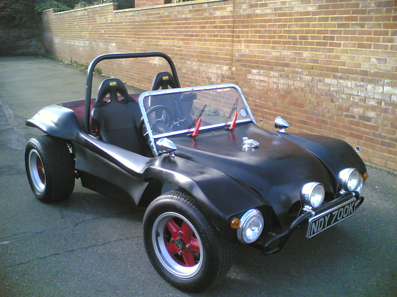
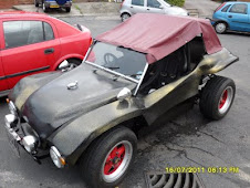
I had been lucky enough to purchase a Paris Beetles Roof conversion for a beetle and was hopping it could be made to fit my buggy. It was immediately noticeable to me that the hoops that where originally for the beetle conversion seemed to fit exactly around the outside of the buggy rear seating area. The top hoop rose high above the roll bar and seemed to be a good fit. This seemed very strange as I could not understand for one instance why they would be the same as the buggy was considerably smaller than the Beetle. I fixed the hoops in place and started to put the roof fabric onto the bars. Found that if I pulled the roof out to the rear of the passenger seat are that the hood seemed to fit nicely around the rear of the car with out much overhang than you would normally expect. This was as you can imagine becoming a little surreal as I was starting to believe I had discovered a cheap solution to fitting hoods on Beach Buggies knowing that most of the Beach buggies body's where historically derived from the Manx buggies. I started by fastening the poppers to the rear apron. I used 4mm stainless bolts to bolt them in position using the center button on the roof to start I worked using the position on the fabric and then the relative position to the body to ensure my button positions . This meant that with the roof not fitted the studs ran evenly around the back of the buggy. This seemed to fit as if it had been made by a custom hood company I was amazed. i fitted the hood to the bars and to the rear clipping it round I pulled the roof ward to the windscreen and clipped it onto studs that screwed onto the window frame . I the cloth was quite baggy but still service able. I decided that if i wanted it tight on te buggy I would need to loose some material from the front. I found that the rag top was 16cm to long. I noticed that the seam at the front was quite simply constructed . The edge had been bound with fabric and the button poppers had all been sewed to a piece of fabric , which then had been sewed to the roof This looked quite easy to replicate so I started to disassemble the front of the hood by un-stitching the seams with a sharp pair of small scissors. Some time later I had the pieces apart and I had the fixings on one piece the edging and the bare front of the roof assembly. Prior to removing the fabric with the studs on I had marked its position with chalk to give me a reference from the original length. I used these marks to measure and draw a chalk line on the underneath of the roof fabric so that I could measure back 14cm the distance from the buttons to the edge minus the reduction i needed. This meant i needed to remove 14cm of cloth from the edge I used a chalk line to draw this cutting line on the roof and set about cutting it off. I noticed that the fabric with the poppers on only had one straight interface edge on it and used this edge on the front of my new cut edge. I used the center button to locate the position of this strip placing it in the center of the fabric. Do not assume that the length of this is the same on each side as mine was not and the center reference popper is a better position marker. From some previous experience with trying to sew leather clothing I new that a normal sewing machine would not cope with the thickness of the material . I decided to take the roof to a dry cleaning company that I new had a strong industrial machine. They agreed to sew the three fabric pieces together for £15.00. I picked up the roof a few days later. The roof fitted perfectly. I was amazed. The head height was superb and I could easily sit in the buggy without banging my head on the roof. I put the seats in place and you can see how much head room is available with the extra 80mm of the body lift working fantastically. I was amazed that from a £50 purchase on eBay plus the £15 sewing costs that I now had a roof that would have cost me in excess of £1000 pounds to have made.
Posted by
Martin
What have you to say?
7 VIEWERS CLICKED HERE TO COMMENT ON THIS POST. ADD YOUR COMMENT.
Fixing the tank bonnet and windcreen
7th June 2011.
I new my petrol gauge had been seriously out and decided that it was about time that this was sorted. I started looking into the mechanism that I had purchased from Just Kanpers some time before. Fortunately I had the opportunity with the tank removed to measure the tanks internal depth from this sender and found that it was 19cm from the opening of the sender. My sender seemed to be completely the wrong length for this and ended up with the post 100mm down and a 90mm long arm to the float. I also realized whilst doing this that my return petrol feed was not sub merged and put a 10mm copper compression joint onto it sending the return petrol to the bottom of the tank. I decided I would also place some of the wiring in for the injection engine I was trying to build. With the tank issues resolved it was bolted into the body work. ready for the bonnet and dash to be fitted. The bonnet now painted sat much higher than it did before the supports where fitted I had to increase the length of the fuel hose to the tank refill opening to allow it to fit. I was then helped by a friend John to fit the bonnet and windscreen to the buggy as I did not want to do this on my own and scratch my new paintwork.
I had found a soft top for a beetle on Ebay and was hoping that I could get it to fit the buggy.
Subscribe to:
Posts (Atom)