Search This Blog

No Charge and Replacing The Alternator for a Bosh Unit

26th January 2007.
I had been having difficulty keeping the car battery charged on the buggy. Initially I thought this was because the engine was never run properly as it was garaged. I bought a further battery and charged them in rotation. I was not sure that a good run would not dry out the alternator and allow the battery to charge , however I had not been able to give the car a run. A short run when the sunshine eventually came out proved that the charging system was not functional and that either the wiring was faulty or the Alternator had died.

There are only three wires connected to an alternator in this case my original unit was a Motorola. One wire feed the charge to the battery, one wire was an earth and the third wire was a positive supply through the ignition light that feed the primary coils. A few checks with my multimeter proved that the wiring was intact and the alternator was at fault.

I removed the Alternator that afternoon the progress of this was very slow as its a fairly large procedure to remove the item. The problem being that the fan housing needs to be removed and this of course means that many ancillary items have to come off to to get it loose. Primarily the one carb and linkage kit and the fan thermostat and associated tinware. The idea is to undo the bolts holding the alternator to the fan housing and undo the bolts on the alternator pedestal and the alternator strap which hold the alternator onto the pedestal. To get to any of this my fan cover had to be removed first.

Once I had the Alternator removed I decided to strip it down and see if there was a fault with the brushes or bearings. The Alternator was not very old and had seen not much where so I was not surprised to see the bearings solid. Additionally the brushes where accessible by removing a plate from the top of the Alternator. This whole section comes out and clearly the brushes where in very good hart to. I could see that the coils were not black and could only presume that the fault was with the regulator circuitry.

I contacted several companies for a replacement and found that the best price I could get for a replacement swap out would be £91.00 and this was from a friends company. I put my Alternator back together and took it over to him to as this was an exchange unit price.

Several days later Rob called and said the Alternator was in. I drove over an picked it up and was surprised that it seemed a little smaller.

The installation of the Alternator is the reverse of the removal process. The Fan housing needs to be propped up a little by would so that it creates enough room to get the Alternator and stand in place. Usually 1 1/2 inches is OK and the Alternator and stand can be placed in situe.

Once the Alternator an stand are in place they stand can be bolted down and the fan housing can be lowered back in place. This can take a little jiggle as the fan housing is a tight fit between the cylinder shrouds a screw driver is useful to pry them apart whilst the fan finds its seating. Ensure you have not trapped the thermostat flap control rod as this needs to pass through cylinder #1 and #2 down to the thermostat. The thermostat screws onto this rod and then bolts into a frame which is secured to the engine block.

Once in the Bosch Alternator was a much nicer unit. When I had manufactured my fan housing I had had real problem securing it as it vibrated on the Alternator . The Bosch unit had a ring around the edge of the unit that my fan housing fitted into beautifully.

Once the unit is in I turned the engine over by hand to ensure that nothing was grating or grinding. Once this was OK I turned the engine over and the engine fired into life. The initial voltage through to the battery was 12v and I wondered why the battery was not showing 14v . I flicked the throttle and the voltage increased 14.5v the battery was charging and my problem was solved.

Installing a Toad Cat 1 Alarm into the Buggy

24th Sep 2006.
I won the Toad Ai606 Alarm on a eBay auction I paid £80 for an alarm comprising of the instructions unlock code and wiring harness. I had previously wired up the whole buggy so I was very familiar with the wiring that was in place. I new that would need to get the outer case to enable the alarm to have a Cat 1 insurance status. I contacted an alarm supplier and purchased this for around £10.00. The alarm wiring was quite easy to follow as the previous owner had labeled the wires up. Most alarm wiring is black and if this had not been done there would have been no way of wiring in the alarm without buying a new wiring harness which would have been very expensive. I wired up the alarm to match my buggy's electronic wiring and test ran it. The alarm worked perfectly. I would have to build a firm position for the alarm to be placed on. (Obviously I have not placed any pictures on here for security purposes.) I made the bracket from a sheet of stainless and fixed it in position. When siting this it is important not to put the electronics in a position where they will hit the other components like the windscreen motor.

I had taken advice about the ultrasonics and had been advised not to fit them in a convert able. The solution seemed to be to fit a two stage proximity alarm and solve the problems. I also fitted a knock alarm at the same time.

The alarm installation was installed over the course of a weekend and I was very happy with the result. The hand held transmitters worked the alarm well and light up the indicators when it was engaged or turned off. I was happier that I could leave the car anywhere and not worry about someone getting inside it. A pager unit was added that send out a message saying the alarm had sounded and what had triggered it.

I was nearly ready for a M.O.T I just needed to spray the other drivers side panel and solve the emission and carburettor tuning problems.

Parts Used
Toad Thatcham Ai606 Cat 1
Toad Dual Zone Microwave Sensor
Toad Dual Stage Shock Sensor
Toad Pager


Installing Side panels

17th May 2006
I bought the side pods of eBay with a lot of competition from other people one was later to be a friend called David who I had met later on the Beach Buggy Web site. The GP panels were in good condition and I had been told that they would fit with some work.

As I was no longer a stranger to fibre glassing this was not going to cause a problem. The first problem was establishing which way round they went as it was not clear from the panels and they where not marked pointed out the correct.

I spoke to several friends that cleared up the problem about which way round they were to be fitted. I offered up the panels to the buggy's and could see that they would need some correction to be fitted. The back edge of the side pods seemed to be OK but the fronts needed about 2" removed from the side to allow the to fit under the lip of the buggy shell. I removed this with an angle grinder until my Kipor generator failed and then by using a conventional saw. My Kipor was just over a year old and to be honest I am not very impressed with this companies products and in my opinion I would not waste money on their products in future, enough said.

I had managed to cut the side pods down and they now fitted. Now I needed to find a way of mounding them on the chassis. It was obvious that I could make right angle brackets that would fit under the front of the side pod and attach them to the body. I used two of these and this enabled a front fixing.

I made a bracket in the shape of a Z piece I could mount this to the underneath of the perimeter body mount bolts and this would project forward enough to allow a bolt to be screwed up through the base of the side pod to attach the bottom to the chassis. I placed four of these made from stainless steel on each side and this seemed to firmly fix the side pods in place. I was not sure whether to make rear mounts and decided that I would leave this to a later date when I had some more stainless steel.

The side pods look great but I had to paint them the fitted well onto the chassis and I believed they improved the overall look of the car to give it a better finish. With the addition of the side pods the affect was good and when they were going to be great when they where painted black . My beach buggy was starting to get finished and I could see the possibility that it might be on the road really soon. I needed to paint the side pods and ensure that the car would pass an MOT and I needed to test all of the electrics and ensure the engine was workable. I had an intermittent fault on the front lights and was not sure why they would not always turn on. I was not sure why I was having to charge the battery so often and wondered if my wiring was correct here. The list was smaller but I new from prior experience things can take longer to achieve than you think.

Altering the rake of the windscreen angle.

15th April 2006.
I did not know exactly how the windscreen fitted onto the car and initially fastened it to the dashboard , I was not aware that it need to go over the bonnet and fasten the back end down. However fitting the screen to the car allowed me to see how the screen fitted to the car and how the dash board and the steering wheel interacted with each other. It was quite lucky that I did this and took some pictures as my local Beach Buggy Group at http://www.beachbuggy.org.uk/ commented on the suggesting the rake of the windscreen looked the wrong angle. This was odd as the bolt holes where already in place in the dashboard. This was further clear to me when the distance from the steering wheel was measured to the screen . There was only an inch between the edge of the wheel and the glass , this was clearly not satisfactory.

I removed the screen and looked at the dash frame. It had been made out what looked like metal right angle brackets this had been welded onto the dash frame to bring it forward . I placed the bonnet on the car and checked the bonnet holes . Funny enough there was holes in the right place for the bonnet to fix. It looked as if I had picked the wrong holes. Whilst having the bonnet on the car It was noticeable how difficult it was going to be to do nuts up in the inside of the dashboard to bolt on the screen and bonnet. I decided that I would have to make a solution to hold the nuts in place. My initial idea was to use my Nut insertion kit to place a nut in the hole. It was soon clear that because the frame was made from two strips of metal that this would not work as one of the holes went between the two pieces of metal. The only solution was to make up a backing plate that had nuts welded onto it. Once in place a third bolt would hold the plate with the nuts in place securely so that the bonnet and the screen could be fitted and a screw driver through the hole would position the backing plate with the nuts on so that a bolt could be inserted.

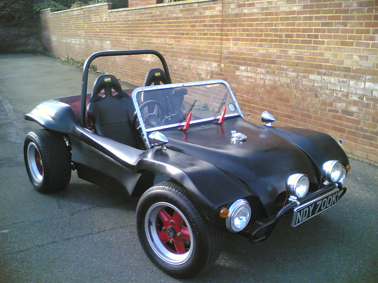
The procedure was a good one and by the end of afternoon I had the bonnet and windscreen on the buggy. As the sun went down I was very pleased with my work. My SWB Rat started to look like a car for the first time and was actually driveable although I still had a lot to do. I had purchased some GP side pods from ebay and wanted to fit them. I also wanted to get the car running properly as it was still backfiring and not running correctly.

Wiring Re-Visited Part One

14th April 2006
I managed to start looking at the wiring that had so far been heavily neglected due to its complexity. During the preliminary work on the car I had wired up the Alternator and starter motor loop through to the battery. I had also taken my wiring loom that I had purchased and placed the ignition coil leads and a small fuse box into the loom. This looked awful and to be honest nothing liked I thought it would. Even the fuse box although a new blade type was too small to take all of the connections. An interesting thing to pass on here is to get the largest fuse box that you can. The stock VW one is the absolute minimum needed and don't be conned by over zealous electrical companies stating 10 ways is enough.

I had downloaded wiring diagrams from http://www.vintagebus.com/wiring/ and had been pouring over the circuits during the Christmas period when it was to cold to get near the garage. I had decided that the wiring that I had in the loom was not enough to complete a wiring solution to reach the rear lights and the front lights. It seemed that the best solution for this was to go to my friendly Beetle breakers and buy two lighting wiring harnesses. These where fairly easy to extract and came with a short run of cabling for the brake switch. I also purchased a VW fuse box at the same time and decided that as this had the mountings for the relays built in that I was going to use it to rewire the car. I wired the lighting circuit in to the fuse box relatively easily. The wiring diagrams where very good as they were colour coded. I managed to buy different colours of wires that matched the wiring colours in the diagrams. This I felt would make the process easier. My helpful beetle braking friend Rob was also able to supply the connector blocks that VW used to connect multiple wires together making a neat job.

The next wiring needed was to hook up the power to my array of dials and the lighting circuits to them. This was to take a while to make them as I had to solder two wires into each spade connector and ensure a clear cover was on each before starting the next. The power wires had six connectors and a seventh to connect onto the circuit on the fuse box or the light switch. This repeated for the earths and again twice more for the instruments lights. The wiring was soon in and connected up. I had decided to stick with the VW switches as these Lent authenticity to the project build. It wasn't long before I had instrument lights working from the button.

I had kept the ignition switch wiring and was able to connect this onto the fuse box to provide a basic ignition system through the key. The rest of the front circuits to the car where connected up as described in the wiring diagram. There was a lot of little wires that linked the circuits together and soon I had front indicators, front lights and hazards all working on the front circuit.

The rear original wiring loom was still in place and as I had the front of the wiring completed I needed to strip the extra wiring out of the harness. This was simply a job of ensuring that I left the wiring colour coded wires in for the rear lights number plate, indicators, brake lights and a reversing light. The resulting bundle was re-wound with tape and laid through the cockpit on the passenger side.

I installed a stereo system in the whole that I had constructed in the dash the wiring was fairly simple and I ran a power amp wire alongside the wiring harness.

I would have to wait until I managed to buy the rear lights before I could start the wiring of the rear lights although I had enough wire to run out to the back of the car and supply the lights when eventually had them fitted. It would not know that it would be until the 11 Sep 2006 until I found some lights that would fit and would be what I wanted for my buggy.

Cleaning Up and Rebuilding the windscreen.

13th april 2006
The windscreen for the buggy is a aluminium frame with a glass panel held in with a rail and right angle brackets. Although simple in design it is a complicated item not to be underestimated.

My screen surround had seen better days and I wanted to take it apart so that I could get the holes in the frame welded up and the hole frame polished and chromed. The rubbers had also seen better days and would need replacing.

The frame is held together by two screws that are underneath the rail that sits on the body. To get at them the body gasket rubber has to be removed and pulled out of its channel. Undoing these screws will allow the rail to be taken off and removed. This then allows access to the glass which should still have a rubber seal around it. The other side of the brackets can be undone by undoing the screws on the outside of the wind screen hoop. The windscreen glass can then removed from its frame by slightly pulling on the hoop to release the screen.

It is very important to take the screen and place it somewhere where it will not be disturbed. Getting replacement glass is very difficult and very expensive.

I collected up the rubber and bagged it so that I could take it to the rubber specialist at a later date.

The screen surround had seen better days and was riddled with different holes for mounting everything from a rear view mirror to a tax disc. I new that it was possible to weld Aluminium and I also new it wasn't for the light hearted so decided to ask some of my friends to see if they new anyone that had welded aluminium in the past. Luckily a good friend Martyn turned up a friend that could weld the aluminium. I took the frame over to him and left the frame with him for a week. In the mean time I decided that my time was better used locating replacement rubbers for the windscreen.

I Located a company called Baines in Tunbridge Wells who were a rubber extrusion manufacturing company. The trip to Baines was pretty successful, although the process of matching the rubber was an interesting one. The company used books of different profiles of rubber each with a number that located its stock. I spent the whole morning here and eventually managed to locate a match for the rubbers.

I got home and had been left a message saying that the frame had been welded and it was ready for collection the next day. The new rubbers fitted the glass but the overall size of the rubber glass combination seemed to be thicker. I presumed this was because the rubber had been compressed for along time in the frame and hoped it would not present a problem.

I picked up the screen surround the next day and took them into my polishers . He agreed to polish it up but was hesitant about chroming it. The process to chrome aluminium requires that the item needs to be cleaned , Zinc-8 coated and the chrome plated. Apparently there are not many companies who have large Zinc8 electroplating baths. I had to settle with my polisher cleaning up the frame. The cleaning process took several days, I picked up the frame and was very happy with the results the frame looked new.

The following afternoon I decided to try to install the glass back in the the frame. I had two sash cramps and hoped that this would squeeze in the glass. Plenty of washing up liquid frustration and black coated hands later it was apparent that this was not the process that go the glass in in the first place. My screen was in bits and I had no idea how to put it back together, my best efforts had be thwarted.

I decided that the windscreen had had to have been assembled and this meant that the only reason that I could not put it together was because I did not know the correct process. I started phoning around and eventually came across a custom car company that specialised in MG open top cars, these had a similar windscreen and It was clear by what the owner said that he could put it back together for £50.00 that he knew something that i didn't.

I left the parts with him and waited for his call.

A week later he called to say that the windscreen was complete. I went down to Eastbourne and collected it from him. I was curious how he had achieved to get it back together as my best efforts had failed. He explained that the secret was in how you assembled it. He went on to explain that he had placed the rubbers in position as I had done. He explained the reason that I had failed was that I needed a method of cranking the frame together. He said he had used four car luggage straps that have a cranking arm to tighten them. He slowly introduced pressure on all of these after using washing up solution as a lubricant over the period of the week he had tightened the straps slowly easing the glass and rubber into the frame. I was amazed that the solution was so simple, but happy my windscreen was back together looking fabulous.