 23rd July 2008.
With the IRS conversion finished and looking fantastic I decided that it would be a shame to fit the rear drums back onto the buggy. Even though I had fitted Bus slave cylinders to the drums they would not still perform as well as a disk set-up. I had always wanted to see if it was possible to convert the rear end. I new that it was possible to cut the rear drums down to make them into rotors but information was very vague at best on which disk or where it could be got from that would allow the rear cut down drum hubs to take a disk rotor. I new that the old porshe 914 had a four stud solid disk with the same PCD130/4 but as the car was now very old sourcing these disks would need a great deal of effort.

Luckily some friends on VZi had been discussing their rear disk conversions with me and one member of VZI was kind enough to mail me a picture with the disk sizes on it. I was then able to they to contact disk vendors with the correct sizes. My search took me to a German company CSP at first they where unwilling to help with the sizes stating that the disks they sold where for their own disk calliper set ups. I eventually took the plunge and ordered a pair of the disks from their online web site only to find that the disks where not in stock and that they had had them on back order for at least 6 months. I cancelled the order and was beginning to think that the disks where no longer available. I started looking online on Porshe web sites and eventually came up with a company called Berlyn Services:
http://www.partsforporsche.co.uk/ . I managed to find the rotors on their website and telephoned them to see if this was another lead to a company that had no stock. To my astonishment the gentleman said that they had some arriving in the next week. I placed an order and was surprised to see the disk turn up very next week.

With the disks in my possession I was able to mount them onto my cut down rotors. I had previously cut down my drums to 210mm or 6" this was a good fit although in retrospect I would have made them slightly larger. This would better facilitate the rotor screws that hold the rotor onto the hub. Mine where very close to the edge and I would probably re-visit this at a later date. Unfortunately I made the decision to cut them without having access to the disks.
My contact at VZI had come up trumps again saying that he had a pair of calliper brackets for Golf callipers. I persuaded him to let me have them and they arrived by post freshly painted thanks 914Baja.
My callipers came from Ebay and were Mk4 Audi callipers from an A3-A6, 2003 although similar to the Golf Mk4 Callipers there are still a few differences like the 12mm inlet feed , bigger pistons and a bigger brake carriers. It was soon apparent that the brake carriers that I had where the wrong size for the brackets. I purchased another set of brake carriers and found these where different size brake carriers too. It was obvious that these all where different sizes dependant on the vehicle manufacturer. I would have to re-work the disk calliper adapter bracket so that it would allow the Audi calliper to bolt on.

I bolted the calliper bracket onto the rear axle so that I could scribe a line down the side of the bearing cover. This would be the closest that the new metal work could come to the axle and still allow the bracket to fit. With this information
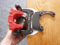
I was able to place the brake carrier of the calliper on the bracket leaving 2mm. This gave me a rough shape to cut the bracket down to. The 10mm steel cut very easily with one of these ultra thin 4 " angle grinder cutting disks. With this material cut of I could place a piece of paper around the calliper and d

raw around it to give me the shape of the metal that I was going to need to make so that it could be securely welded onto the first bracket. With the metal adaption cut out from 20mm steel I could trial fit it onto the existing bracket with the axle cover to check I had enough clearance I secured this with a clamp ready for grinding and welding. With a position established I could draw

the position of the first axle part onto the new 20mm flange. This would allow me to grind off a diagonal onto all the surfaces that met. The idea of this was to ensure that the weld penetrated right into the metal join. The two parts where then re-clampe

d with the axle cover plate and welded with an arc welder. The brackets where ready for their first trial fitting. With the brackets bolted onto the car and the disks mounted onto the disk stubs it was apparent that the calliper brake carrier had a wedge profile that would mean the bracket would need to be made the same profile as this to allow the Calliper to fit. I decided that this was too complicated and cut the bracket down so that it stayed within the flat portion of the calliper but still gave some strength to the bracket. The calip

er brake carrier now mounted squarely onto the bracket. I drilled and placed two high tensile bolts through the bracket to ensure it would not fail. I replaced the bracket onto the car to see if the brackets where now correct to align the brake carrier onto the disk. It soon was apparent that the brake carrier disk recess fouled the disk. I would need to have the face of the brackets milled to remove material from the face. To be honest getting the right amount of material to be milled of is quit difficult and it took me two trips to the milling company before I got the mounts to fit. Originally I took 3mm of the front face but when I tightened up the disk it still did bind on the brake carrier. Another 2mm took me to the right position and from the original 20mm It came down to 15mm with a 5mm step.
With the disk and callipers mounted and freely turning I was able to fit the brake pads to the callipers The beauty of the Golf/Audi callipers is that they are captive and the pads just fit alongside the brake carrier whilst the calliper is slipped over them and bolted up. There is a lot of procedures online for changing brake pads and I will not bore you with this detail.
 Brake Callipers fitted but not plumbed in.
The next job was to fit the hard lines for the brakes and the handbrakes I ordered in some copper brake pipe long enough to connect up the calliper. I soon realized that this would not work as the calliper had a 12mm inlet thread. The main reason for this was that as the calliper was a floating type on calliper slides it needed to be able to freely move. A lot of other websites showing conversion make this same mistake and I would have to order in the correct Audi hoses.
The new hoses would require a new bracket to be welded or fixed onto the A-ARM that would capture the end of the hose. I would need to fabricate this from steel and mount it onto the A-Arm at the correct position. I planned to try an bolt it onto the A-Arm but thought that it would probably need to be welded. I still had not resolved the problem of welding in the garage and new removing the A-Arms was a lot of work.

I started the fabrication process by removing the cable from the bracket further up the A-Arm . With the bracket free of pipework I was able to offer up a piece of paper the would allow me to draw an outline around it. This gave me the rough shape of the bracket I needed. I decided to add a little material to the bott

om so that I could bend it over and form a rail that could be screw. In the picture you can see the bracket shape stuck onto the steel plate. I made the brackets from an old piece of right angle peice of metal. This was roughly big enough to make the two brackets. I drilled four holes in the bar so that the bend would be on the diameter of half of one of the holes to make it easier to bend. I would need to determine the position of the brackets first by buying the hoses from GSF. With the hoses I was able to screw one end into the calliper and work out that the bracket would need to be placed 0" from the end of the A-Arm end. This was a good site as it was not goint to interfere with the axle. With the brackets cut out I decided that I would have enough room to screw them to the A-Arm.


Whilst I was making up the brackets I decided to check the clearence of the brake calliper with the wheel fitted. I was not sure how tight this would be against the rim. Although this was tight because of the weights that the balancing company had used there was enough clearence. With the wheel fitted you could also see that the angle that the wheel sat had changed due the the
IRS conversion. This would present the wheel width in its entirity onto the road surfice improving grip and conering speed.
I was having trouble locating the rear hoses as they where 12mm inlet callipers instead of the normal 10mm. Whilst searching for the hoses I bought th4e GTI Golf Handbrake cables. These are much higher quality as they have an inside plastic tupe that the brake line runs inside. I had to take the plastic end of of the cable so that I could shorten the rigid part of the cable. I removed the cap with a small screwdriver slowly prising it off the rigid pipe. This allowed me to measure up the rigid part of the cable and strip the plastic off so that I could cut internal steel with a hacksaw. The cap could then be carefully put back on with some washing up liquid neat applied to the parts. Once I had the cables cut down to 640mm each side. I realised that the metal end of the conduit that the cable ran through would not fit into the calliper hole. I luckily bought a 9/16" drill to allow me to tap the case oil gantries. I used this to drill the calliper cable holder so that the metal end would fit snugly.
Parts to build the Rear disks
Steel Sheet
- 20mm x 180 £10.00
- 10mm x 240 £10.00
A-ARM hoses GSF Car parts numbers
10mm Caliper hoses GSF Car parts numbers
- 10mm banjo offside 657VG0620 £14.00 + Vat, or VAG 1J0611763L
- 10mm banjo nearside 657VG0610 £14.00 + Vat or VAG 1jo611764L
or 12mm Caliper hoses LC Davis & Son Ltd part numbers
- 12mm banjo hoses PHD350 £18.07ea
Hand Brake cables Golf GTI GSF Car parts numbers(With the conduit cut down to 640mm)
Disk Rotors Berlyn codes
- 2 x 914.352.401.10 Porshe 914 130/4 10mm £49.00 + vat ea
Total Cost £ 201 + callipers and pads of your choice.
Audi A3-A6 Rear Callipers
The installation cost me well under the normal kit costs available from most suppliers to convert my rear drums to a professional sliding calliper disk set-up. There are more expensive kits available from retailers that cost more than this and offer less in functionality. I managed to source the parts I needed at differant prices than the prices I have given, which are a guide should you buy your parts through regular channels.
I found out some time later that VW Type 3 rear disk rotor carriers are available. I bought a set of eBay for £30.00 and will intend to fit them in place of my custom turned down versions later 2009.
My Callipers
LUCAS REAR BRAKE CALIPERS AND MOUNTS CAME FROM A 02 REG PASSAT 130 SPORT TDI SHOULD FIT SIMILER AUDI A4 AND OTHER PASSATS ARE IN GOOD WORKING ORDER, VW PART NUMBERS ON THE CALIPERS ARE 8E0615424/8E0615423 THE PART NUMBER ON THE CARIERS ARE 8E0615425F ANY QUESTIONS PLEASE EMAIL ME OR CALL 07854 392717, THANKS FOR LOOKING
pr code 1kf
Hoses for calliper 4b0611775c
Hoses for calliper 4b0611775 as kindly provided by GSF
 25th July 2008
 than 250 miles since its last rebuild and there was no way of retrieving it other than dismantling the engine. Firstly I must say a thanks to the informed members of VZI who stated not only where the parts would end up but where they would get mashed and what they would destroy if left in situe. To be quite frank they stated the exact position. The yellow arrow points to where the bits ended up. This is just under the timing gear on the camshaft. The green arrow shows the oil feed to the crankshaft. The red arrow shows the lower pump ring that the Bakelite pump bush fits into.
 removed the barrels could be removed taking special care to get them out so far that the gudgeon pins could be removed and the pistons removed still attached to the barrels. This is a little tricky but with a pair of long nose pliers to remove the circlips the pistons can be removed by sliding out the gudgeon pins. These can sometimes be a little st
 iff and a warm air blower like a paint stripper is enough to gently warm the piston to make the pin slide out again. With the pistons and barrels removed the main pulley can be undone at the front of the engine. If this is tight then the flywheel will need to be locked in position. Personally I tried to use a bar between two bolts and still resorted to buying the correct tool from eBay. This fits into the top engine bolt and securely holds the flywheel so that the front pulley and then flywheel nut can be undone. The short block is then able to be split. I removed the cylinder studs and the oil pump and the oil strainer first to allow better access to the case. There are eight large 17mm bolts and a large number of 13mm bolts around the case that all need to be undone. Make sure that you have got to all the 13mm bolts as there are some that are hidden tight against the back of the fly wheel and also in other hard to get to areas. With all the engine nuts undone . The case will still be stuck together. You will need a rubber mallet or a piece of wood and a hammer to carefully knock the case apart generally speaking its easier to lay the engine on a block of wood on its left hand side so the eight large studs are facing you. There are several good places around the case that you can hit , which will break the case seal. Once you have the case halves separated you can draw the top half on the engine case of the bottom. This will expose all of the internal workings of the engine so make sure you have a large quantity of rags or cloths that you can mop up the oil slick that comes out. Before going further you need to retrieve the cam followers that have fallen into the bottom case. You also need to check that you have two dots on the crankshaft camshaft timing gear and one on the camshaft gear. these are vital to lining up the engine timing, when the hole engine is put back together. Once this has been determined remove the camshaft and cam bearings and place them in a box. Carefully lift out the crankshaft with the con rods and put this in another box with some rags to soak up the oil. You need to ensure that you have all of the bearing halves out of the engine.
 Next I will remove the oil plugs and re-thread them to allow fo
 r any eventuality that the engine needs in the future. I ordered the brass screw caps 3 x 3/8 NPT , 2 x 1/4NPT , 5 x 1/8th online from http://www.airlink-compressors.co.uk/Fittings/plugs.htm, unfortunatly thier website ordering was down and I had to telephone the order through. In the mean time I had to find a 9/16 drill bit and a 1/32 or American R size drill. I choose the 11/32 as I already had one. The next challange was to locate the taps. My tap set came with a 1/8NPT trap but finding a 1/4NPT or never mind a 3/8" NPT tap was going to be a challange. I posted a wanted advert on VZI to see if anyone had any.







 Posts
Posts


