Search This Blog

New Year Move

31st December 2010
The last year has been filled with family problems that will not how ever much I try see to get them resolved. This has had a major affect on my motivation and the time I have spent on my project as of late.

I was very surprised to have a knock on my door two days ago when a really good friend came round to see which rock I was hiding as he not seen me for a long time. It was soon discussed that I could move the buggy from my garage to another nearby making it easier to work on it. My friend said he would help me move the Beach Buggy and today this actually happened.

I am quite excited about some of the things that where discussed and hopefully 2011 will be a more interesting year.

GOD BLESS YOU JOHN

HAPPY NEW YEAR EVERYONE

Final Suspension parts

12th October 2010
With this month full of planning for my daughters birthday there was not a lot of time spare to work on my Buggy, this was compounded as it was the traditional bonfire season in the UK. The reality of this was that there was very little that I could do.

I did however locate and purchase some front suspension arms. These were obviously mucky and in much need of restoration. I would have to renew all the ball joints. Which meant I had to get the old ball joints out. I had spent some time on the Internet researching different methods for removing the ball joints but had found none that I felt competent with, that would not damage the arms.

I started the clean up operation by scrapping the mud and soil debris from the arms. I then used Gunk to clean the grease and dirt from the arms.

Collecting Parts

10th September 2010

Not much has been done to the buggy since the body lift kit was made for it. The family issues I had been experiencing had distracted me from my buggy. Instead I have been collecting front suspension parts as I new the body lift would require the front suspension top be dropped. I purchased a new beam from eBay which had been already reconditioned. I also bought a set of new spindels with a 2/1/2 " drop on them as I felt the best solution to this was to make up an entirely new front beam and then sell the old one off afterwards. I also bought some second hand control arms but have been experiencing problems getting them shipped from the seller due to the seller not providing information for the courier. I hope that this will be sorted shortly.

I still needed to resolve the problems with my engine and it was clear to me that it would have to come out so that the problems could be resolved. This was something I seemed unable to gather energy for at present.

Manufacturing a body lift kit - part four

19th June 2010
The previous weeks have been very busy and I have not had the opportunity nor the weather to get the body lift kit cut down and welded. Fortunately there was a small break in my time that coincided with reasonable whether albeit raining to all all the rails to be cut down and cramped to the chassis prior to welding.

I had previously spent some time trying to neaten up the welding this actually was costly in time. As when I was improving the welds I found that the heat I had applied to the curves had reshaped the curves so they no longer fitted. The only option was to cut new slices into the rails and re weld whilst the section was cramped to the chassis. This worked very well and it appeared both sides had warped due to this clean up. The picture right shows the cuts that were made and welded up to bring the curves back in line. Once the curves were cut the side pieces were cut to length. This was achieved by placing both front and back sections on the chassis and marking their positions on the chassis. This could then be transferred onto the side bars and the cuts where made to match the profile of the front and back sections where they mated. The front sections where fairly square the rear sections approach the side at a slight angle. This required a 5-6mm angle to be cut onto the side rail. A friend came by who uses a MIG welder and wanted to try ARC welding As I new the outer sections would need flushing I let him try his hand. Fortunately he made a pretty good job.

The welds where soon completed and the body lift frame was left on the chassis to cool down in preparation to a clean down with a grinder. Four end plates where cut out and cleaned up so that they could be welded into the ends of the body lift kit tubing. This would keep the moisture out of the tubes and make the section solid. The perimeter holes would then be needed to be marked from the underneath the chassis and the center punched and drilled. Once the welds where cleaned up the whole body lift frame would be prepped to be taken to be hot zinc sprayed and then blacked. This process was the best way of stopping the steel from rusting as it was used successfully on bumpers and roll bar parts to keep them clean. The process was original developed for 4x4 bumpers as the knocks ride of the zinc coating and the item can just be re blacked to bring it back to the same finish.

The most important thing I found when building this is that the curves cannot be made my bending the tubing. If you try this yourself you will find your body will not fit on top as the top of the tubing curved radius will be different to the bottom. Originally I thought I would have this manufactured at about £150.00 . The materials cost £50 for the 75mm box tubing 3m length. 20 cutting disks £20.00, and 100 welding rods. I would imagine having completed this it would have cost me £350.00 - £450.00 to have had built from the same materials.

Manufacturing a body lift kit - part three

20th May 2010

My welding mask arrived quite quickly along with some rods that I had purchased from eBay . I decided to start welding up the back section first as this seemed the simplest. The three pieces were cramped to the chassis and butted up i ground a V in all the joints so that I could get more weld in them and therefore get a stronger joint. These were soon to run out but luckily Lidl was selling a welder and welding rods I bought 4 boxes on chance for £3.95 they are superb and I am very surprised.

Front and back sections.
I started with the curve in the back section I made very small triangle pieces out of the box section to fill the area between the slits this held the position of the curve and allowed the weld to maintain it self . This was repeated until the whole curve was welded up. You can see from the picture the inner face was smooth as it required no welding whilst the outer surfaces would require grinding. the rear diagonals were all then fitted to the donor chassis and cramped in position so that the rear section could be welded. This proved quite successful I had cut a section out of each side to fit snugly into the rear chassis section. This was all tacked and welded. The middle curve section was then dropped in and the whole section was tacked and then welded up. I was very pleased with the result of this as this was a technically challenging part to make up as it had a lot of curves and bends in its construction. The rear section was then fully welded up and the whole rear section was retried on the rear of the chassis cross member. The next sections would again require cramping the new frame to the chassis. I welded up the curve of each of the front section so that it could check it on the chassis I used thin slivers of cut tubing in a wedge shape so as to not have to infill with so much weld. It was a pretty good fit. The front two halves could then be welded together whist cramped to the chassis. Once the two halves was welded together it was noticeable that one of the lower leg angles had moved due to the heat of the welding this angle was cut back out by using an angle grinder and the new angle was welded together again to make a good fit. The finished version was obviously incorrect as the top curve was totally wrong. I new this would not fit the chassis. I drew an initial template from the bottom of the section. When I superimposed it on the top It was noticeable that the curve needed to be at least another 1/2" higher. I stated fabricating a new top by making a new curve section that would fit the bottom. I made this extend further into the bend so that It would clear the existing welding. This was then welded up to make a solid curve. I was able to then position this on the top of the curve to allow me to mark the union of the two pieces this was quite complicated but surprisingly went very easy. You can see in the diagram left I have cut the two sections so that they mated seamlessly into the curve of the welded front section. The difference in the previous and the new curve is immediately noticeable. I tested this design on the body and chassis of a donor vehicle to my horror the whole top section was still wrong. Further analysis proved that there was a strange phenomenon happening. It appeared as if the sloping sections of the front section had to be thinner than the 80mm box to keep the same shape and profile as the bottom of the front piece. It looked on paper that these needed to be 12.3mm thinner. This was completely unbelievable. But yet with the top lowered 12.3mm the top would again fit the bottom of the section like it should. After a while scratching my head I decided the only reason for this had to be that the slopes vertical diagonal component had to be 80mm and this was the reason the width had to be reduced by 12.3mm. This was a very iimportant discovery as it meant the rear section may not be correct either. The math for this was also simpler than I thought it was basic trigonometry a jotting pad soon came up with the mathematics needed to find the new height required on the diagonal components based on the angle that the diagonal was leaving the vertical. Looking at the rear section this was also wrong and needed changing as clearly the end sections was wrong and not following the contour of the top either.

Front section finalized.
I new that I would have to lower the peek of the front section by 12.3 mm. To achieve this I would need to cut out this new section from the front all the way down to the flat ends. I would then have to remove 12.3mm and re weld the whole assembly back up . The picture right shows the top half lowered by 12.3 mm . This gives a vertical height in the middle of 80mm. Which is correct and now fits the body work perfectly. This would also need to be done for the rear section which is a much more complicated section. I would have to work again from the angle to the horizontal and use a trigonometry tan function to work out the new height. One really interesting thing about all of this is that the number of people that told me to get the tubing bent to make this would have all been wrong as this would not allow the body work to fit in the same way as my previous methods had not.

Rear Section finalized.
The rear section was with the new mathematical information also wrong the angle it raised from the horizontal was 20 degrees . Using trigonometry (80 mm/(cos 20) = 85.1 mm ) - 80 mm = 5.1mm shorter in the diagonal heights. It can bee seen from the photo left that the original rear section I had made fitted the bottom beautifully but the ends of the section where wrong and too short on the top section. This meant also the height of the tubing needed shortening by 5 mm. I started by marking out the cuts to each side diagonal and the increase in end required. With this I was able to cut the top of the diagonals and shorten the box tubing by 5mm. This also gave enough distance for the end pieces to be extended.

Two opposing side sections.
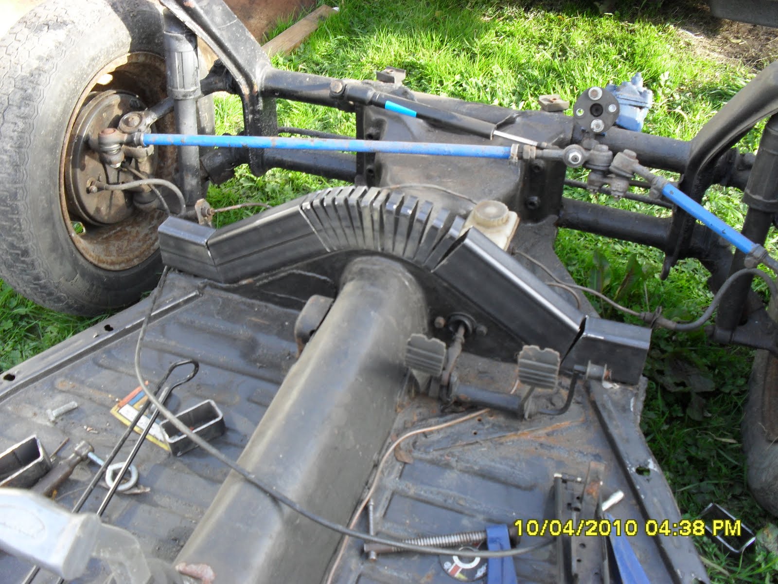
The side sections were much easier to fabricate to shape I cramped the side sections to the chassis and ensured they matched the curves in the chassis. I ensured that the lengths where longer than I required so that they could be trim to size. I cramped the rear section first and then moved forward placing new cramps to ensure the shape was correctly held in place. Some gaps where to large to weld so I used the cut out triangles from the rear section that I cut out and welded them into the larger gaps. This process yielded a much cleaner weld and it can be seen that it held the section together better. With this repeated for both sides the design was starting to come to shape. I tacked both sides so that they could be transported and welded up in a warmer environment. You can see with both sides cramped in situe the strength of this new section was already stiffening up the chassis. The picture left shows the two side sections tacked together before they were removed to be fully welded.

This was becoming a lot more complicated structure to build than I had figured I would need to cut the sections to shape and weld them up to make a complete chassis. This will be continued in the next episode.

Manufacturing a body lift kit - part two

10th April 2010
As I started to ponder the front and back sections of the body lift frame. I realized as I looked at the chassis that there was in fact more curves than I had originally seen when I appraised these sections. Specifically at the back I had tried to cut a section to fit the side rail by using a bevel gauge to find the angle. On revisiting the chassis it was evident that this was wrong as there was a very small angle 20 degrees at the end of the rear run sections that made the tubing hit it when it sat square along the chassis. Obviously this affected the way it was constructed. I cut the length of each diagonal on the rear of the chassis at 55mm which allowed a small overhang so that it could be trimmed when I had cut the curved top piece to make it fit flush for welding. I then measured 50 mm up each length and marked a center point to cut a triangle out to make the lower angle using trigonometry (tan 20) * 80 mm I worked out the base would need to be 28 mm. I measured and cut this triangle section out and bent the metal to form the correct angle . The curved section that sat around the access panel for the gear lever linkage was going to need to be created entirely on a curve. This would prove to be one of the most difficult pieces to get correct as there was no way to cramp it to the chassis to hold its shape like I had done with the other parts to weld them. The process of getting this curve took some time to get correct as it had to be accurate as the brake line ran directly behind it. I cut the back inspection plate curve at 20 mm intervals there was twenty cuts needed to form the semi circle curve. The rear section bottom angle was made by cutting one 30 mm piece out of the top edge of the box centered on 50 mm from the end of the tubing this gave enough material to be removed to create an angle of 20 degrees. The mitre between the diagonal upright and the curve section was very difficult to get to fit neatly luckily I had a very good friend John to help me and we eventually managed to get a reasonable fit. The front box section I decided was going to be needed to be constructed in two sections. The reason for this was it would be easier to construct two curves each side instead of four in one piece of box section. This allowed for the pieces to be cut and marked so achieving a good curve going over the tunnel that represented the original as much as possible. The lower angle approaching the tunnel was measured at 35 degrees using trigonometry (tan 35 degrees) * 80 mm I calculated that a triangle of 58 mm on the top base edge was required . I then cut slits at 10 mm intervals to allow the rest of the metal to be curved. The front two sections where then cut so the butted up to each other in the center. as you can see at this point the front and back sides had not been trimmed to length. I decided that the two curves front on back were stable enough to be welded off the car chassis. This was good as I wanted to get some experience of welding this material and in filling the gaps I had created with the slits. I knew I would need this as when I returned with the welded section sections I would have a large welding tacking job at hand. The picture right shows all the parts cut to shape. Some of the parts would need to be shortened after the sections front and back where joined together on the chassis. The reason for this was to try to ensure the parts hugged the chassis neatly. With everything cut I was waiting for a replacement welding helmet to turn up so that I could start welding. I was very pleased with the work and the help of my friend both with some of the difficult pieces and the use of his chassis to fabricate this lift kit onto. Whilst waiting for my welding helmet to arrive I noticed that the radius of the curves on the front cross section where different radius's top and bottom of the middle section. This would mean the front section would need the top of it to be remade to the same radius at the bottom. I decided this was something I could do once it was welded.