I knew that with the increased engine performance I was adding to the buggy that I would have to strengthen the
FibreFab body panels as compared to modern equivalents the body thickness was a lot thinner and lighter. As a result of this I knew the biggest area without support had to be the rear seat area. Since I had cut this to facilitate the
CSP Torque bar I knew that it was in desperate need of something sturdy to hold it up. Previously I had fitted a heavy duty cradle and this had a flattened bottom section that looked like it was made to take a 30mm tubular cross beam. With this and some galvanised farm gate hinges I set out to make a strong body rear mount that would fix to the gearbox cradle.
I bought the galvanised gate hinges from a local farm store t

hey were pretty inexpensive too under £10.00 for the pair. I bought some 20mm x 1.5mm x 90mm bolts to hold them together from my local bolt specialist. The 30mm x 30mm x 2mm tubular section on the other hand was something that I was finding hard to locate. My stock piles had long since gone with several moves , eventually I found a suitable item a towing bar that was made from galvanised steel this was exactly what I was looking for. I cut a section of the 30mm x 30mm x 2mm tube 40cm long and held it against the gearbox cradle to mark the locations of the bolt holes.
I packed
th
e farm gate hinges with three zinc plated washers. I used a
nyloc nut to secure it all together and cut the end of the bolt to shorten it to 15mm longer than the face of the
nyloc nut. I repeated this twice. When I bought the farm gate hinges I bought more nuts than I needed . The reason for this was that I was going to have to grind some of the nuts down so that they were square and would fit inside the inch tube. Once the nut would fit inside the tube four holes were drilled in the 30mm x 30mm x 2mm tubing so that they could be puddle welded. It was immediately apparent that the gate hinges would need more than one support in the 30mm x 30mm x 2mm tube so I started about making three more square washers from the hexagon nuts. This was made easier by using a vice clamp to hold the nut whilst using an angle grinder to flatten the surface. The next
proble
m that I realised was going to be positioning the two nuts in the tube prior to welding and also allow them to thread up OK. I decided the only way to achieve this was going to be to have to drill the locating holes in the 30mm x 30mm x 2mm tube first. This meant putting the nuts onto the thread and spacing them and positioning them on top of the 30mm x 30mm x 2mm tube so that the position for the puddle weld holes could be marked and d

rilled. With the holes cross drilled the nuts could be reinserted into the tube. The thread of the gate hinge was then used to position them and the nut and the tube was drilled to get a better puddle weld that would penetrate into the nut. The puddle welds were then done on opposing sides so as to keep the tube square. This was repeated for the other opposing sides to secure the two nuts. The same process was done for the other end of the 30mm x 30mm x 2mm tube making the base for the body mount ready to fit. The farm gate hinges would just screw in so that they would provide an angled threaded section up towards the rear seated area. I originally thought that 10mm bolts would hold it but the weight and size of the holes in the cradle has made me consider 12mm or 14mm bolts instead. The 14mm holes were drilled after the picture was taken.

I made the diagonal risers from 25mm x25mm x 2mm square tubing slightly smaller than the 30mm x 30mm x 2mm as its was the material remaining from the towing bar kit. I welded the nuts onto the end of the bar to make an
upriser that would reach just below the bodywork. I also left part of the hook that attached the bar to the car so that the nut could be welded firmly onto it I cut half circle sections into one face of the nut so that it would fit the remnant bar and give a good contact area for welding. I felt this should be made of lighter material as the double skin I had used for the base was heavy but strong. I was intending to make a stainless steel plate that would attach this to the body work, with bolts that went straight through the body work.This would need to have a 'U' shaped
upstand fabricated onto the bracket to receive the bar. Having bolted on the bars It was soon visible that this would not be the answer.
I contemplated using the sections of larger tubing to make a
boltable on end plate that would have the advantage that it could be removed and welded up easily. I was not also sure whether to use an angle iron across the back of the buggy seat area so as to tie the two diagonal uprights together and make a solid section to which things on the seat area could be bolted through too.
I decided after a considerable

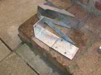
time looking around to buy two galvanised joist hangers these were fairly heavy duty and I had realised that if I removed one side of the hanger I would have a corner piece that would give me a large enough area to weld on a piece of larger diameter tubing that would slip over the diagonal uprights. This in turn could be bolted together making a strong joint that would

give a large mounting area on each side of the body work. The first job was to remove the side of the joist hanger these had been spot welded together so initially I tried drilling them out. I managed to drill deep enough to just remove the weld. The remaining weld could be removed with a hammer and chisel. For a strange unknown reason the second bracket seemed to come apart more easily. The two opposing corner brackets can be seen pictured left without the diagonal bars welded in place. I would have to source some 30mm x 30mm x 2mm square tubing to make the diagonal guides as I only had one piece remaining from the tow bar.
In addition the area the engine was going to come into was

becoming quite crowded and I needed to ensure that none of my new pipe work interfered with the engine cylinders or exhaust system. I decided to make up a wooden template that would hang off the gearbox final drive so that the position of the new bars could be determined and then placed on the back of the engine to see if the new metal work impinged on any of the engine before the brackets were welded up. The images show that the wooden template was made from thin fence slats cut down to 35mm wide. The drop from my final drive to the top of the bracket was 200mm. The narrowest point was 23mm fr
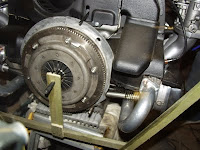
om the centre point. I drilled the ends to make the angle adjustable and set it using a gauge to be the same as the angle coming of the bottom bracket. You can see that the bracket misses the exhaust. Phew! With this all checked and the constraints off the engine taken into account the brackets could be welded. It is important to note that different exhausts have different profiles and may extend into this area in different ways. Ensure you check your exhaust configuration in a similar manner otherwise you may not be able to refit your engine..

With both sides removed I trimmed off the surplus material and placed the corner piece on the buggy and slid on the larger diameter tubing so that I could mark the angle that this needed to be welded. This was then repeated to mark the opposite bracket. Both brackets were then removed and the galvanised surface removed for the welding to adhere. They were then welded taking care not to warp the steel in the process. The Galvanized coating was quite
difficult to weld even with the surface removed so it was vital an area along t

he join had to be ground out.
The corner brackets where then cleaned up on a wire brush and the welds thoroughly checked. they were then mounted on the buggy and checked for position. It can be seen from the picture right that some changes had to be made to the adjustment screws to get the angles the same on each side. Originally
the left bracket kicked up a little because of the
difference in angle. Suitable mounting points were determined and marked so both brackets could be removed so that they could be drilled. 4 holes were dr

illed into the side plate big enough to ta
ke a 10mm bolt. One of the holes went right through the diagonal upright securing it to the body and mount. The parts were re assembled with 10mm bolts. Suitable large washers were also found to stop the body work chafing on the bolt heads. Ideally the items should b

e re zinc coated. The finished mount was very strong and could take a heavier load in the rear seating area. It also eliminated the flex that is
inherent in fibre glass body panels.
The next step would be to ensure the gel coats were added to the newly fibre glassed areas prior to the engine going back in.
 28 Feb 2010
 ns. The major of these was a 3" body lift kit. I had been asking on several websites about the Bugpack kit but had been told that it was not as strong as a box section version. This meant that I had to have one made which would take some time to be fabricated. The good thing was at least my engine would be run in prior to the fitment of the turbo. It would also allow me to fit an electric fuel pump in front of fitting the turbo and check the systems work.
 jets but no 112 main jets. I started removing the turbo and exhaust from the engine and started to clean up and paint the previous exhaust I had used. the Carplan VHT paint was fantastic and bought the exhaust up like new. I hoped the new main jets could be located soon but would have to wait to source the parts. I found the new jets and continued
 to paint up the rusty exhaust. There would be some fitting issues possibly with the braketry but this would have to be sorted out after fitting. I hoped my new body mount would not be obstructing the old exhaust as it had been modeled to fit the drag exhaust. The fitting or changing of the exhaust from the turbo collector was undead a problem The no3 cylinder J tube was tight on the Heavy Duty Gearbox cradle and at first would not move. This eventually came free with the help of a friend John and the next problem was also evident. The new body support I had built was right in line with this new exhaust. I decided as as I was trying to have the 3" body lift kit made that th
 is would have to change anyway as the whole body would rise 3" making the support arms the wrong length and angle. I removed them and refitted the drag link bars that now fitted. The bracket that held the oil filter was also directly in the path of the new exhaust. I made a new bracket that placed the external oil filter lower by using the old one i had manufactured as a template. The resulting bracket can be seen left. With the bracket made I could now refit the oil filter . I now needed to start work on the electronics to run my electric fuel pump. The electric design had been given to me by a VIZI member and I was intended to fit the new electric pump I had bought with a return flow to the tank ready for the turbo to go back in.







 Posts
Posts


