Search This Blog

Building the battery fastening device.

25th Feb 2007.
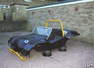
OK before we start no Darth Vader or Daft Ader comments or wow that's an improvement. Caught in the act !

The day before I had spent the day looking around the buggy looking for jobs that needed to be completed before the M.O.T. This culminated with the front number plate being fastened to the bumper with self tapping screws and the formulation of the idea of a way to hold the battery in place as I had been recently told that the MOT regulation requires that the battery be able to stay in position with the vehicle upside down. I decided to sketch out some ideas that could be constructed from some angle iron. The premis was simple as i needed to have a bar across the battery and then some screws down each end that would hook into a base. The base could be constructed from a frame welded from 1" angle iron, the top from 1/2 angle iron and the securing bolts from 6mm steel rod.

I cut the 1" angle iron with an angle grinder so that I had one of the angles removed and a flat piece of steel about 6" long. The end I made up from 5" of angle iron and drilled a hole in the centre to take the bolt. I new this would needing welding and only had my trusty Sealey Mig 100XT to weld it as my Arc welder was at my fathers. I had not used the Mig for a while so as with all Mig welders it needed a clean up before I attempted to weld with it. The welding material was rusty and this had to be removed until clean material was available and the tensioner had to be adjusted. You should never attempt to weld with a MIG welder that has rusty wire as it can block up the welder and causes the mechanism to slip as the rust acts as a lubricant.

I welded the framework up easily welding both sides of the frame to provide a good weld. This made a nice solid base and I finished the welding on the first end and was soon onto the other end. I am glad I cleaned up the MIG as it was performing beautifully and creating good solid welds on the Angle Iron. You can see in the picture opposite that the base of the battery compartment was taking shape. I cleaned the welds up with my Angle Grinder and packed the welding equipment away and returned to the garage.

Now you may ask why I welded at my house when most of you are aware that I have a 2.7KW Honda Generator, the trouble is the MIG seems to use about 2.8kw at peak and the welder trips out. I will have to service the generator at some point and try this again as most information on the net says this combination should work.

In the garage I heated up the rod ends and bent them over in a vice. I took the battery out of the buggy and placed it on top of my frame. This gave me a height that my screws would have to be. I cut the rod down to this length plus one inch and then tapped tapped a thread on each with a 6mm metric die. The bar was cut to length and the rods could be inserted. I drilled the base so that it could be fixed to the fibre glass.

The frame looked great and I took it back to the house with the in tension of taking it to my Zinc plater AC Blastings, who provide a hot Zinc spray process. This would take a while and I intended to get it to them on Monday.

Another tunning attempt in the garage thwarted

18th Feb 2006

I returned to the garage after changing my carburetor linkage the following day. I was full of expectation as I hoped that if I could get the carburetors ticking over that tuning would also be possible. I opened up the garage and started up the buggy and was pleased to hear the most wonderful puring noise at 900 r.p.m . One of my friends John had come over with his buggy and it was nice to show him my progress. A short demonstration ride , however brought to my attention another problem that was getting worse on a daily basis. My gear changes where becoming impossible and reverse was giving the most awful grinding noise.

I suspected this to be the clutch and hoped it was just the adjustment as I had about 3" on the pedal. I knew this procedure was fairly long winded as it involved removing one of the large rear wheels to gain access. The wheel came off fairly easily and gave access to the clutch lever under the body work. The cable had been shortened with a shortening kit and looked like it had worked loose. The nut that held the cable in place was loose and was not trapping the cable correctly. I took the shortening kit of and after lubricating it , checked to see if the nuts went up and down on the threads easily.

The shortening kit fitted back on to the cable easily I had bent the cable with two pairs of pliers the shortening kit sat in this new loop. I was able to tighten the nut onto the cables by holding the cable in the pliers whilst doing up the 19mm spanner. The shortening kit was then slotted back into the clutch arm and the butterfly nut was tightened down to allow 1/2 - 3/4" pedal travel.

I then had to replace the rear wheel. This is always a difficult task as it means the car must be jacked at exactly the right height to facilitate the wheel being aligned with the bolt threads. This took me over an hour to achieve and with having to lift the wheel a little to get one then all four nuts started. I tightened the bolts down hard and then took the car of the jack.

I needed to run the car out to straighten the suspension so the wheels settled back down. The clutch was working fine.

Unfortunately I had used up my petrol allowance for this week and therefore could not tune the tune the car I locked up and went home.

Another day with the linkage kit

17th Feb 2006

Today was a day of trial and tribulations and to be honest a day off trying to get the car to tick over at 900 r.p.m. The reason for this low rpm was because my gear box would not easily select reverse when the engine was reving. My Engine had been ticking over at 1200 r.p.m which was a little to fast and I had to bring it down.

I had previously improved the linkage kit by improving the amounts of thread on the adjusters so they had plenty of movement. This however was unable alone to get my r.p.m down. Despite making lots of adjustments the engine still settled after full throttle at the 1200 r.p.m spot. I decided that I needed to pull the linkage back to its stops with some heavier springs. The carburetter linkage bearing plates had a small hole that an extension spring could be positioned in. The right hand carburetor had a hole on the throttle leaver that the other end of the extension spring would fit into . This stiffened up the right hand side. The left did not have a hole so I removed the throttle leaver and drilled a 1/8 hole in it so that the spring would fit. With my new return mechanism in place I thought this would resolve the r.p.m problem , However I was to find that the car still reved at 1100 r.p.m.

I spent some time checking the linkage kit tightening it up so that I had very little movement in it at this point I noticed that the right hand carburetor was the point of trouble. It had a smaller throttle lever and this was not returning. It was late in the evening and I had to leave the problem for the moment as I had run the battery out starting and stopping the car the number of times that I had. I would have to return to this problem another day.

I decided to visit the garage later to pick up the battery to charge it properly. Whilst there I pondered the linkage some more the springs held the left hand side back against the stop and the left was just coming short. The result of this was the right hand carburettor was supplying more fuel at idle. I adjusted the rod so that it was shorter so it pulled up the distance I would have to return with the battery charged and see if this resolved the r.p.m problem but it looked promising.

Tuning Attempt one

15th Feb 2006

I decided that after fitting the new spark plugs I would have another attempt at tuning up the engine. The baseline setting I had for the mixture screws were 2 turns out from bottomed. Before I ventured to the car I spent some time reading on the Internet I looked at the Redline Weber web site :http://www.redlineweber.com/html/Tech/idf_adjustment_controls.htm and saw that the mixture screws here for baseline were one turn out, this was a lot more than my previous article had stated. I decided to look further and found an excellent article on jetting, and synchronising: http://www.aircooled.net/gnrlsite/resource/articles.htm . The air cooled website had some very useful information abed out jetting which contradicted the print-out that I had about jetting. It suggest that my main jet should be smaller a 50 idle jet , were I had a 55. It also suggested my main jet should be 1.17 were it was 1.30, my Emulsion tubes were correct . The article went on to say that the spitting and spluttering that I was seeing ad high revs was due to the main jet being to lean and needing to be go bigger. My Air corrector was set to 2.00 and the crackling exhaust noises could also be attributed to the the jet being to lean and it suggests a 1.80 jet.

This all sounded interesting reading and to be honest was something I was going to have to look into further obviously the Redline jetting was a guide and not a completed solution. I would have to find out were I could buy main, idle and Air corrector jets to try this and this was going to have to be picked up another day.

I got out to the garage and decided to ensure that my idle was set OK and that the linkage kit was well balanced I started by looking at the down adjusters that adjust the position and balance of the linkage kit. The left arm did not have much track on it for adjustment. I decide to remove the ball joints and run the car without the linkage kit. This enabled me to set the carburetor idle screws up for each carb to try to balance them out. I had read somewhere that using a 1/2 tube across the top of each ram tube would enable you to hear the difference between the carburetter pulling on each side. The interesting thing was that you could hear the tappets drumming too.

I shortened the left adjuster taking care to thread the correct end. This is important as only one of the threads can be thread with conventional taps and dies as the other is a left hand thread. Threading down the wrong end with the idea of then shortening it would severely brake the adjuster. I checked and checked again the end threaded it with a 5mm die further down replaced the nut and then cut the end off the rod. This fitted beautifully and allowed a lot more movement for adjustment. The afternoon was going well I warmed up the engine and set the mixture screws up at 1 1/2 turns out. The car was starting to run better. I still had the pops and crackles at hi revs and believed i needed some more information. I would contact Air Cooled and see if they would make a recommendation differant to what I learnt from their site.

Fitting Platinum NGK Spark plugs

13th Feb 2007
I found whilst trying to tune the dual Weber IDF carbs that my cylinders where not all firing. I tracked this down to cylinder #1 spark plug not firing. I foolishly borrowed a plug from a friend only to find out when I decided that they all needed replacing that the plug I had used was a long reach plug. Initial horror of the piston hitting the spark plug was solved by doing a cylinder head pressure test. This still was mystifying as it did not explain why I had short reach Bosch plugs in long reach cylinders. I decided that I would have to investigate the cylinder heads further . I found an old C.K vernier gauge and bent the end of the tail of it over so that it was at a right angle to the depth gauge. With the plug out on cylinder #1 I was able to hook this under the threads and measure the distance to the top thread, this came about at between 16-17mm. Clearly I had bought Mexican 040 heads with long reach spark plug threads.

I noticed that whilst the plugs were in the car that the was a high degree of petrol in the emission from the exhaust. This inferred that the plugs were not burning all the petrol in the heads. Although this was possible caused by the short plugs in the longs threads I wanted to uprate the plugs to produce a better spark and decided that I would have to telephone NGK to find the correct plug to suit my engine.

I rang NGK and asked them about the different types of plugs that would fit my long reach thread engine heads. I asked about the quad,triple, Iridium and V type plugs. I explained that I wanted more spark in the cylinder head. The tech guy told me that the quad and triple electrode plugs did not always fire to every electrode and fired randomly, he went on to say that this would not provide a larger ignition over the cylinder. He suggested The V type plugs or Iridium or Platinum would be an option however there was no V type plugs that would fit my cylinders. He eventually suggested the NGK BP5EVX which where platinum plated long reach plugs.

I telephoned around my care tuning and accessories company's to no avail and eventually tracked them down on eBay.

The spark plugs arrived one week later and I was able to fit them quite quickly, however during fitting process I broke one of the stainless spark leads that I had paid over £50 for some years earlier . I was amazed to see how poorly they where constructed and that they were not well made. I removed the metal sleeve from the rubber spark plug cover and checked the end of the lead the centre of the lead was not broken and it looked as if it had never been soldered to the metal sleeve. I re crimped the sleeve back on leaving the centre lead touching the sleeve as it was on the other leads. I replaced the rubber sleeve using washing up solution. After washing and drying the lead to remove the washing up liquid from the end I re-fitted it and fired up the engine.

The engine fired up and I instantly noticed that the fuel residue in the exhausts had disappeared. It was clear that the carburetors still needed tuning and I left this to another day.

Parts Used
4 x NGK BP5EVX Platinum Spark Plugs.