Search This Blog

Fitting the turbo lump to the strengthened gearbox - part one

12th December 2009.
The installation of my turbo engine back into my buggy was something that I had long awaited. I had had the engine with some parts mounted for the turbo sometime ago but it was going to be interesting fitting the completed engine and my spirits were high as I new with it fitted I only had to plumb the fuel up to the engine through the new pump to get the engine fired up.

From the onset this proved more difficult than I had underestimated the extra height the pressure caps took and the cross air intake ducting had took the engine height much higher. I decided I would have to jack the rear of the car up and allow the engine to go under the rear boot area. This soon became difficult and I realised that the caps and engine would not fit under the engine compartment. In addition there seemed to be some interference with the ceramic drag exhaust and the CSP Torque bar. The exhaust J tube went right through where the torque bar anchored. My own bar that I had made up to support the rear seat area fitted perfectly.

I decided that I would have to remove the CSP Torque bar diagonal triangulations to the frame horns and remove the pressure ducting and caps so that the engine would fit and the Clarence issues could be seen. The engine fitted perfectly after these items had been removed. I had enlisted some friends to help me lift the engine.

With the engine fitted the top of the carburetors and the clearance can be seen in the photograph to the left. It can bee seen that the wooden block and the lower tear of the back was obstructing the pressure caps from going on. It was clear I would need to do some re modeling of the rear to allow for these parts to be fitted. In addition I knew that the CSP Torque bar would never fit with these J tubes I wondered if different tubes could be made up which would not interfere with the CSP Torque bar.
I was gutted my turbo engine refit was slowly turning into a disaster and a new list of jobs to complete. I started looking at the rear body work on an attempt to figure how to modify the rear of the buggy to allow the components to be fitted. I new I would have to sketch out some ideas for this before starting to cut the rear end and re-fibreglass it to shape. I tried to see whether I could modify the rear of the chassis by moving up the rear wing. This looked like the most easiest and best option and would mean with careful cutting the approximate shape could still be captured giving enough clearance underneath for the new turbo pressure ducting system. I would have to remove the engine and cut the fibreglass before re-bonding it in place. |The photo above shows the approximate difference with the area moved up. You must ignore the lover light clusters which would not be there after the wings were highered. I used a photo to see how it would look.

Body work and Gel coating the rear seating area

18th November 2009
Since making my rear body support I had noticed that the rear seating area that it attached to on the left side was not allowing it to sit straight. This was mainly caused by the fibre glass seat area work that I had undertaken in Mad March affairs with the CSP Torque bar installation and rear body modification but not been able to get access to. Luckily with the engine still out I was able to dismantle the body support and the torque bar to give access to the area under the seat. Where I had moulded the shape on cardboard sections there had been some seapage underneath that was obstructing the off side body support bracket. I used a rotary disk sanding attachment for my drill with an 80 grade disk. This cut the area back so that it was in line with the bottom panel. The process was slow going but rewarding as it gradually came back in shape.

The next problem was going to be how to remove the gel coat from the areas where I wanted to fibre glass were they were very close to the chassis or suspension. I had to think about this as I didn't want to spend a lot of money buying a Black and Decker rotary file. I remembered using a carpet layers knife in the past and set out to see if I could find one to see if I could cut the old gel coat off in slices.

When I cleaned up the left hand side I noticed that the bracket came back into orientation. I had to fill the holes I had made to mount it originally, I cut the surounding area down with the rotary sander from both sides and re fibre glassed from both sides to make a strong bond and re drill to bolt to its new location.

I was going to try to get my grey gel coat in a jar from the last place I got it made up a small fibre glass company. Unfortunately I believed they had moved on so a new search was on to find another company that would be so reciprocating. The red I thought would only come from one source as its not used commercially or so I thought. Luckily a search using the Yell search engine provided me with a surprise that the company Castle Mouldings I had purchased the original gel coat was still trading and would happily still sell me gel coat. This was great news and the gel coat was applied using a brush to the new fibre glassed panels. The red was quite a bright colour and hoped that it would merge with the existing coat overtime as the grey had done some years previously. I used about 5% catalyst with the gel coat as it was quite cold . I mixed up the grey gel coat and coated the underneath of the seat area. Some of the underneath was not accessable and I new I would have to attend to this at a later date. After considering the areas I had gel coated I decided to cover the whole rear seating area. The fibre glassing work that had been done on the underneath of the body whilst on the car had not been done as neatly as I would have liked with the body removed. I am hoping that at some point in the future this can be re addressed.

I also managed to sell my twin manifolds and linkage kit I had bought prior to deciding to go turbo. This was going to be helpful as I hoped it would allow me to buy an inter cooler for the engine. The search was now also on to find one. I was not sure after searching through the classifieds online whether this was going to be easy.

Manufacturing a buggy rear body mount

29th Oct 2009.
I knew that with the increased engine performance I was adding to the buggy that I would have to strengthen the FibreFab body panels as compared to modern equivalents the body thickness was a lot thinner and lighter. As a result of this I knew the biggest area without support had to be the rear seat area. Since I had cut this to facilitate the CSP Torque bar I knew that it was in desperate need of something sturdy to hold it up. Previously I had fitted a heavy duty cradle and this had a flattened bottom section that looked like it was made to take a 30mm tubular cross beam. With this and some galvanised farm gate hinges I set out to make a strong body rear mount that would fix to the gearbox cradle.

I bought the galvanised gate hinges from a local farm store they were pretty inexpensive too under £10.00 for the pair. I bought some 20mm x 1.5mm x 90mm bolts to hold them together from my local bolt specialist. The 30mm x 30mm x 2mm tubular section on the other hand was something that I was finding hard to locate. My stock piles had long since gone with several moves , eventually I found a suitable item a towing bar that was made from galvanised steel this was exactly what I was looking for. I cut a section of the 30mm x 30mm x 2mm tube 40cm long and held it against the gearbox cradle to mark the locations of the bolt holes.

I packed the farm gate hinges with three zinc plated washers. I used a nyloc nut to secure it all together and cut the end of the bolt to shorten it to 15mm longer than the face of the nyloc nut. I repeated this twice. When I bought the farm gate hinges I bought more nuts than I needed . The reason for this was that I was going to have to grind some of the nuts down so that they were square and would fit inside the inch tube. Once the nut would fit inside the tube four holes were drilled in the 30mm x 30mm x 2mm tubing so that they could be puddle welded. It was immediately apparent that the gate hinges would need more than one support in the 30mm x 30mm x 2mm tube so I started about making three more square washers from the hexagon nuts. This was made easier by using a vice clamp to hold the nut whilst using an angle grinder to flatten the surface. The next problem that I realised was going to be positioning the two nuts in the tube prior to welding and also allow them to thread up OK. I decided the only way to achieve this was going to be to have to drill the locating holes in the 30mm x 30mm x 2mm tube first. This meant putting the nuts onto the thread and spacing them and positioning them on top of the 30mm x 30mm x 2mm tube so that the position for the puddle weld holes could be marked and drilled. With the holes cross drilled the nuts could be reinserted into the tube. The thread of the gate hinge was then used to position them and the nut and the tube was drilled to get a better puddle weld that would penetrate into the nut. The puddle welds were then done on opposing sides so as to keep the tube square. This was repeated for the other opposing sides to secure the two nuts. The same process was done for the other end of the 30mm x 30mm x 2mm tube making the base for the body mount ready to fit. The farm gate hinges would just screw in so that they would provide an angled threaded section up towards the rear seated area. I originally thought that 10mm bolts would hold it but the weight and size of the holes in the cradle has made me consider 12mm or 14mm bolts instead. The 14mm holes were drilled after the picture was taken.

I made the diagonal risers from 25mm x25mm x 2mm square tubing slightly smaller than the 30mm x 30mm x 2mm as its was the material remaining from the towing bar kit. I welded the nuts onto the end of the bar to make an upriser that would reach just below the bodywork. I also left part of the hook that attached the bar to the car so that the nut could be welded firmly onto it I cut half circle sections into one face of the nut so that it would fit the remnant bar and give a good contact area for welding. I felt this should be made of lighter material as the double skin I had used for the base was heavy but strong. I was intending to make a stainless steel plate that would attach this to the body work, with bolts that went straight through the body work.This would need to have a 'U' shaped upstand fabricated onto the bracket to receive the bar. Having bolted on the bars It was soon visible that this would not be the answer.

I contemplated using the sections of larger tubing to make a boltable on end plate that would have the advantage that it could be removed and welded up easily. I was not also sure whether to use an angle iron across the back of the buggy seat area so as to tie the two diagonal uprights together and make a solid section to which things on the seat area could be bolted through too.

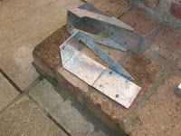
I decided after a considerable time looking around to buy two galvanised joist hangers these were fairly heavy duty and I had realised that if I removed one side of the hanger I would have a corner piece that would give me a large enough area to weld on a piece of larger diameter tubing that would slip over the diagonal uprights. This in turn could be bolted together making a strong joint that would give a large mounting area on each side of the body work. The first job was to remove the side of the joist hanger these had been spot welded together so initially I tried drilling them out. I managed to drill deep enough to just remove the weld. The remaining weld could be removed with a hammer and chisel. For a strange unknown reason the second bracket seemed to come apart more easily. The two opposing corner brackets can be seen pictured left without the diagonal bars welded in place. I would have to source some 30mm x 30mm x 2mm square tubing to make the diagonal guides as I only had one piece remaining from the tow bar.

In addition the area the engine was going to come into was becoming quite crowded and I needed to ensure that none of my new pipe work interfered with the engine cylinders or exhaust system. I decided to make up a wooden template that would hang off the gearbox final drive so that the position of the new bars could be determined and then placed on the back of the engine to see if the new metal work impinged on any of the engine before the brackets were welded up. The images show that the wooden template was made from thin fence slats cut down to 35mm wide. The drop from my final drive to the top of the bracket was 200mm. The narrowest point was 23mm fr
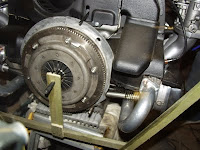
om the centre point. I drilled the ends to make the angle adjustable and set it using a gauge to be the same as the angle coming of the bottom bracket. You can see that the bracket misses the exhaust. Phew! With this all checked and the constraints off the engine taken into account the brackets could be welded. It is important to note that different exhausts have different profiles and may extend into this area in different ways. Ensure you check your exhaust configuration in a similar manner otherwise you may not be able to refit your engine..

With both sides removed I trimmed off the surplus material and placed the corner piece on the buggy and slid on the larger diameter tubing so that I could mark the angle that this needed to be welded. This was then repeated to mark the opposite bracket. Both brackets were then removed and the galvanised surface removed for the welding to adhere. They were then welded taking care not to warp the steel in the process. The Galvanized coating was quite difficult to weld even with the surface removed so it was vital an area along the join had to be ground out.

The corner brackets where then cleaned up on a wire brush and the welds thoroughly checked. they were then mounted on the buggy and checked for position. It can be seen from the picture right that some changes had to be made to the adjustment screws to get the angles the same on each side. Originally the left bracket kicked up a little because of the difference in angle. Suitable mounting points were determined and marked so both brackets could be removed so that they could be drilled. 4 holes were drilled into the side plate big enough to take a 10mm bolt. One of the holes went right through the diagonal upright securing it to the body and mount. The parts were re assembled with 10mm bolts. Suitable large washers were also found to stop the body work chafing on the bolt heads. Ideally the items should be re zinc coated. The finished mount was very strong and could take a heavier load in the rear seating area. It also eliminated the flex that is inherent in fibre glass body panels.

The next step would be to ensure the gel coats were added to the newly fibre glassed areas prior to the engine going back in.

Turbo Baby and unscheduled garage move.

19th October 2009.
My first turbo engine was looking pretty good. I had managed to fit all of the pressure inlets and pressure pipe work to connect the turbo to the carburetors. Luckily I had a length of tube that I could use to connect up the last bit of the inlet to the turbo as really I wanted to fit a Charge cooler or Intercooler but also wanted to get my engine in an running.

I needed to locate a new fuel pump to power the engine as I had removed the mechanical pump so that I could control the fuel flow and not end up with the engine pulling fuel and self feeding itself. I started looking for a Renault 5 turbo fuel pump and regulator. During this time I was made aware of an issue with my tenancy on my garage. This resulted in moving to another garage. The move was a lot easier than I had anticipated as I had many friends help and want to thank them them for thier support. In addition I had managed to buy a towing bar that allowed me to easily tow the car without an engine in it.

I had been also researching different types of charge cooling including the RS500 Pace charge cooler kit and had came across some new ideas using paraffin wax in a charge cooler to keep the cooler temperatures down: http://autospeed.com/cms/title_The-Fusion-Intercooler/A_110772/article.html . This is loosely named the Fusion Intercooler and seems an interesting article. However I could find no further detail of anyone trying this on a VW engine so have put the whole subject of Charge coolers on hold. The original article was written in 2003 some six years ago. The concept seems good but there are no links on the Internet stating it actually works in practice. I am considering trying it out but need a suitable charge cooler which are not cheap.

Dellorto DRLA40 carburetor non linkage return Issue.

27th October 2009
I had been noticing that my left carburetor was not returning to its stop since the rebuild process for the turbo seals whilst I was installing the new linkage kit. I was not entirely happy with the shaft when I put it back during the turbo rebuild and it appeared now I was right and the non return issue on my left carburetor was due to the spindle being bent. This resulted in the shaft rubbing in the carburetor. The only solution I found was to renew the shaft. Its quite tricky to do as you need to be comfortable with stripping the carburetor. The best way to do this is to photograph each stage if you haven done this before. You need to remove the paraphernalia on the top of the carburetor Air cleaners or trumpets. There are 4 screws on the op of the carburetor that hold the float cover on. If you remove these you will most definitely need a new gasket so don't skimp. With the top loose gently remove the top carefully as the float is underneath put these items somewhere safe in a backing tray.

Next remove the two screws either side of the carburetor this locate the spray bar it only goes in one way make sure when you take it out you recognise this. The screw is usually held with a locking nut. With this out the chokes can be removed sometimes these grow in here and will need carburetor cleaner to get the loose and maybe a soft tap. Again look at the orientation how the come out. Record everything

Next remove the nuts on the spindle and remove the control arms these must go on the right way round. Its important that you note which side the longest part of the spindle protrudes from it is imperative it is put back exactly the same for your linkage kit to work.

Next turn the carburetor over you should see the two butterfly valves two of them in each carburetor throat they are held with two brass screws which are peened over on the back so they don't fall out. Once you have the screws out you can twist the spindle vertically so that the butterfly can be removed by sliding them out of the slot. Repeat 4 times noting which way round the butterflies come out and which hole and which way up they will only come out one side. With the butterflies out Put one of the spindle nuts back on the spindle and use a soft rubber mallet like a camping one to remove it. The bearing may come out too don't worry. Use a thin screwdriver to drive it all the way out. You can knock out the bearings whilst your there and remove the plastic covers with a small watchmakers screwdriver and grease the bearings replace the plastic cover.

Put it back is same as dismantling it. Make sure the new shafts the right way round (imperative) I used a couple of sockets or tubing at ether end of the spindle to drive the bearings into their correct seating.

The butterflies can only be inserted from one side of the spindle they wond go in from the other side. Use 4 new brass screws for the butterflies. Peen them from the other side once their tightened by putting a screwdriver across the back of them and tapping the screwdriver with a light hammer ensure you support the shaft underneath with something so as to not bend it again.

Now I did this I now need no springs at all. A carburetor schematic can be found on the www.dellorto.co.uk web site you can buy parts here or on ebay.

Locating Induction inlet pipes & Pressure Covers

20th September 2009

I have been having trouble locating the parts that I needed to complete the turbo 1600 engine I was building. After exhausting every VW specialist in the UK. It was obvious that I would have to spread my search further. Volkzone had initially turned up nothing either as most of the turbo parts come from CB Performance in the USA I knew that with carriage prices currently over $100's I would have to get a UK dealer to order them for me. VWSPEEDSHOP came up trumps again he stated that he could have them here with a month . In the meantime I scoured Vzi and eBay in the hope that something might be available faster. Finally I found someone on Vzi selling a turbo kit that he would split . He had the CB Performance Inlet pipes but no pressure covers.

You can see that the inlet pipes are in two parts they are made from steel which is prone to rust. I painted them as soon as I got them delivered and decided that at a later date I would have them chrome plated.

The VWSPEEDSHOP cover plates were not forth coming as fast as I would have liked. I luckily managed to get an answer to my wanted add on Vzi ,which meant they did not need to come from America, which was causing the delay. I was still not sure whether to fit an inter cooler or cooler to the turbo output. I would have to start connecting up before I would now how much room I have to fit a cooler in. I had also managed to order the silicon connectors from eBay at a substantially reduced cost. I chose the humped connectors as I thought it would make a stronger connection to the pressure covers.

The next problem was going to be assembling all of these components and see weather there was enough room for a water cooler or inter cooler to reduce the turbo air pressure temperatures going in thorough the Dellorto DRLA 40 carburetors.

Linkage kits - Empi - CB and turbo installations

5th September 2009

I had bought a brand new Empi linkage kit a few months back as I already had some inlet manifolds that I was going to use. Unfortunately I had forgotten that the CB pressure covers that were designed to capture the turbo boost and channel it into the carburettor would only fit on the CB linkage kit. This was a major foobar as The Empi Linkage kit had cost quite a lot of money and was a major piece of equipment to get wrong. Fortunately I managed to sell some pieces of beetle parts that I had in the garage that allowed me to purchase the new CB linkage kit and manifolds that I managed to get at a very good price.

The Empi linkage kit uses base plates to sit under the filters and can be seen in the photo right. It is generally quite a good piece of kit with high quality heim joints and aluminium hex cross bar , linkage bar and throttle. The package was very easy to assemble and I was pretty disapointed not to be using it but as there was no system for getting the boosted air into the carburettors with this linkage kit it had be replaced with the CB performance Linkage Kit pictured right. I had negotiated with my dealer not to supply the filters and filter caps as I was not going to use them as I would have to buy turbo pressure caps instead that the dealer had to order specially from the USA which would take a month to arrive.

The most notable thing about the CB kit is the quality of the equipment. Secondly you will notice that the manifolds place the cross bar horizontal to the engine without needing a modified plate like the EMPI system used. This seemed in my opinion to make the engine look more balanced. The fitting instructions see picture right that come with the kit do a pretty good job of explaining how all the parts go together although it did not seem to informative about the hiem joints and I had to purchase some adapters separately to bolt onto the Dellorto throttle levers to enable the adjustment bars to work well. The plates that hold the linkage bar need to have the screws screwed into them to fix the pressure covers it is a good idea to thread lock them into the base, as I have seen a number of these in the past come unscrewed with the bolt locked onto the shaft. The manifolds were an excellent design however no provision for the fitting of a vacuum line to feed the dump valve comes as standard. I found an old pump that had brass feed pipework integral to it. These were extracted from the pump and where fitted into the edge of the manifold by drilling a 5.5mm hole and then with thread locking them in to make a sealed joint. A 3mm silicon hose can them be run to the dump valve . repeated this for both manifolds and used a nylon tee piece to join the two manifolds making one feed to the dump valve.

With the carburettors waiting for the pressure covers to arrive so I could fit the boost system . I would have to turn my attention to the oil system and make some decisions about cooling and supplying oil and retuning oil to the turbo, I would also need to make a bracket to hold the weight of the turbo on the exhaust system.

Dellorto DRLA 40 Carburretors, Jetting and turbo application.

22nd August 2009
I had always used Weber carburettors in the past and was always hearing that Dellorto carburettors were far superior from people who had used them for years. With my new engine now progressed to the long block, I had to decide how I would supply fuel to it. Previously I had a project that consisted of a Garret turbo T3 unit and a drag exhaust that had been extended to work together. None of this had made it onto an engine and I figure that with the new strong block that I had built this would be the best time to bring it all together. With this in mind I new I could not use Weber carburettors as they could not easily be modded for turbo use. I found two Dellorto DRLA40 carburettors online in an auction that originally were from an Alfasud. I new the jetting would be wrong for the 1600 long block, but I figured that the jetting would all change with the turbo anyway so this would not be a problem. The first thing I had to do was to thoroughly clean the DRLA40's up. This is a fairly large job as it does not just entail cleaning the outside of the carburettors . The inside must be stripped down and cleaned thoroughly too. I decided this was the way I was going as I knew that ultrasonic carburettor cleaning techniques although good, would not find broken or missing parts should there be any. Once the carburettors had been thoroughly de-greased with Gunk, I started to dismantle them. The filter covers are bolted to the top of the carburettors, with this removed the top of the carburettors can be seen and access is then available to remove the top screws that hold the two parts of the carburetor together. It is beneficial as well to photograph the components before removing them so that you can easily remember were they go when rebuilding. The top will then come off the carburetor and will take with it the float which is attached to the roof of the carburetor.

I contacted John Maher Racing Ltd ; Mr John Maher in the Outer Hebrides, The isle of Harris. http://www.johnmaherracing.co.uk to ask him if he still could machine the pair of DRLA carburettors for turbo spindle seals. He told me that he still had the equipment to do this but he also said that he could not covert all Dellorto carburettors. He went on to say that you needed a 20mm boss inside the middle of the carburetor to give enough room to take the turbo seals.


He indicated that he had seen carburettors in the past that did not have this and could not be converted. Luckily my carburettors were OK and I sent them of to him. You can see the boss on the inside of the carburettor wall clearly. the picture also shows that unlike the outer bearing which is sealed. the throttle shaft runs straight onto the crab bodywork meaning that the surfaces had no seals to keep fuel in the carburettors under more than atmospheric pressure. The carburettors throttle shafts have to be routed out with a special tool that allows one side of the carburettor body to be done at a time. The picture right show the process of cutting the turbo seals. This is repeated three times for each side as three steps must be cut into the body to allow a plastic washer, o-ring and star washer to be fitted. The whole process is done from the outside of the carburetor with a cutting tool mounted on a spindle that is passed through the existing throttle shaft-hole. The cutter is also supported on the shoulder of the other side of the shaft. Some cutters have a cutting surface on each side. This actually allows the process to be simplified by pushing in and pulling out to do each of the bosses. It is imperative the recesses that are cut true to the throttle shaft .

The picture left shows the machined boss ready to take the turbo washers. It shows the three cuts made into the sidewall of the carburetor. I used the specialist services of John Mayer as I felt that he had the tools to do the job correctly. Obviously this is a risky modification to a carburetor as if the seal leaked then your whole engine could go up in flames very quickly. I ordered my turbo seal kit from Euro Carb http://www.dellorto.com and waited for my carburettors to be returned to me.

My carburettors came back very quickly and I was very happy with the machine work that had been done. I previously had stripped out everything but the throttle body as I wanted to keep the machine costs down. I knew I just had to rebuild the carburettors and had taken some good photographs of the carburettors in various states of being dismantled. The first job was to fit the new turbo seals into the newly machined areas. This seemed at first an easy job as it required fitting the washer and the o-ring followed by the star washer which was pressed into the recess to hold the washer and o-ring in place. My first attempts at this resulted in the star washer pinging back out. I decided that I would use the throttle spindle to line up the washer and o-ring so that the star washer could be pressed into place. I also used a small pair of pliers around the spindle to press the star washer from opposing sides. My patience was soon rewarded and I manged to get the four seals in place and the throttle spindle back in the carburettor with the ball race seal at each end. It is very important when assembling the throttle to match the spindle to the right carburettor side, as the spindle protrudes more on one side to accommodate the levers for the linkage system.

The butterflies could then be fixed to the throttle spindle again paying attention to the way they came out. It is important to put these in carefully as they will not fit if forced and they are very easy to bend. The rest of the carburettors could then be built up . The accelerator pumps were renewed and fitted back in. The other ancillary items where added to the carburettor and all the components where cleaned and assembled as can be seen photograph left:


At this point I had to decide what I was going to do about jetting. Fortunately I had met a gentleman Dan on Volkszone who had turboed his Beetle . He suggested that I should start off with the jetting he had as the cars had a similar specification as he had had his carburettors professionally set up. I bought the turbo conversion kits as they came with the turbo gasket and the high capacity needle valve for the float bowl.


DRLA 40 Aspirated jetting
---------------------------------

  • 4x Venturis 28mm
  • 4 x Main Jets  1.20
  • 4 x Air corrector  1.8
  • 4 x Idle jets 7644  .6
  • 2 x Pump Jet 0.35
  • 2 x Needle Inlet 1.5
  • 2x starter emulsion tubes 7482.3
  • 2x Starter Jet 60
  • 4 x Emulsion tube 7212.2


DRLA 40 Turbo jetting
------------------------
  • 4 x Main Jets 160
  • 4 x Idle Jets 7644.60
  • 4 x DRLA Pump Jet 10927 not DHLA 10927.
  • 4 x Turbo Emulsion tubes 9164.turbo
  • 2x starter emulsion tubes 7482.3
  • 2 x starter jet 3315.80
  • 2 x Air Corrector (short) 7482.170

This was quite a shopping list as the jets and emulsion tubes are only available from a few outlets. Luckily I found some CB Emulsion tubes on eBay that were better than the standard ones. I also found main jets , Idle jets an air corrector from a dealer on eBay: Fast RoadCars. The rest I would have to buy from Euro Carb. It is important to note that some parts can be shared between the DHLA and the DRLA with jets . The exception to this though is the pump jets 10927 which the DRLA uses longer versions than the DHLA.

I was very surprised how expensive the jets and the turbo conversion had cost. In hind sight It would have been cheaper to have bought one already modified but then I don't think I have seen many on the market for sale as in recent times there has been a drive towards efficiency and the carburettor has been surpassed by the injection system. This said the injection system is a whole lot more complicated and I was intending to cut my teeth on a turbo system that had a smaller number of parts to go wrong.

If you are considering doing this conversion to a set of carburettors budget at least £80-£100 for the DRLA 40 carburettors, the machining will cost upwards of £69.00 depending on how they are delivered to JMR, Turbo Conversion gaskets, seals, pump valves and other ancillaries around £96.00 without the re-jetting costs which if you may be able to source the parts from other suppliers.

I would have to purchase a new CB linkage kit for the carburettors as I knew that the CB pressure covers only fitted the CB linkage kit.

Prices current 2009 only.