 28th March 2010.
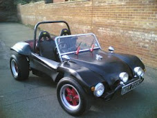
I had been searching the Internet for a body lift kit that would allow the body to be raised on my Buggy so that the pressure ducting from the turbo would fit under the rear of the body. I had originally considered that I would fiberglass the rear body area , but a good friend had suggested this as another option and it was then I realized it would solve two of my problems, the second being head room. I had really not wanted to change the look of the car to much and after looking at different hood designs I was aware that my head would go through a soft top with the current set up. I had thought that I would have to lower my floor pans to allow the seats to be placed lower than the chassis. This is a large amount of work and the body lift kit idea seemed to cater for both problems. I had found that in America I could buy a BugPack body lift kit.
 Pictured left. This seemed a little delicate for my off road requirements so I started to source some material to make the lift kit from.
I found a supplier ARC Fabrication Ltd in Hastings that supplied me with 80mm x
 40xmm 3.1mm x 1.5m lengths this was ideal as I had been told that I needed four to go around the perimeter of the shortened chassis. I picked up the mild steel box section and started to ponder the best way of fitting it around the complex shape of the floor pan.
There was at least six curves to negotiate and luckily a good friend had a chassis that I could build the lift kit onto and was very helpful through the build process. I had put a thread on VZI asking which was the best way to curve the box section as I new there was several ways of achieving this. The consensus was that bending the material put stresses into the side walls of the material and that cutting and welding was a better option.
I decided I would have to see if there was a mathematical rule for calculating the number of cuts and the distance between the cuts to negotiate a curve. I had been told already that the curve on the leading edge of the chassis near the front needed six cuts that where spaced at 20mm intervals apart to negotiate this curve but had no idea how this had been calculated. This meant I needed to research this as I had to get over the tunnel and this was going to be very difficult without some maths to simplify it.
 I started by working on the side rails. Initially these had looked like they only had one curve but in fact they had two on each side. I started by marking the rail were the curve started to come in at the front this gave me a position to start cutting into the rail. I marked the chassis were this mark intersected it so that it could be used as a reference marker to re-align
  the rail in the same position. I then marked out six cut marks 20mm along each rail, so that the 20mm intervals fell around where the curve was going to come. This gave me my cutting marks. Cut the box section using 1mm metal cutting disks these cut quickly t
 through heavy metal. It is very important to wear safety equipment with these cutting disks as they can easily cut through anything quickly. Three sides of the box section was cut so that it lost its rigidity and was able to be bent around the chassis to form an
 even curve.I used the 4" C-cramps to initially cramp the longest side onto the chassis. This gave a fixed point so that the the other half of the box section could be levered into position. I used a piece of wooden batten to pull each of the cuts out so making the distances regular and more easy to weld. The process was then repeated for the other side.
 It was soon noticeable that the box section cut across the front edge of the floor pan. This didn't look very neat and I decided that if another curve going the opposite was was placed at the end it would bring the end of the box section back in line with the chassis. The angle of this curve was much tighter than the previous one and I decided
  to make six cuts at 15mm interval to allow for the tightness of the curve. You can see in the picture opposite that the box section now followed the perimeter of the chassis sides. I had only bought with me a few C-cramps and really did not have enough cramps to cramp both sides down hard. The result of this was that I new I would have to return and complete the front and back sections. I had decided to make the front sections out of two pieces and the rear section out of three pieces. The reason for this was to simplify the curves so that the box section would fit flusher with the chassis. I will return to make the front and rear sections in the next article.
Supplier
Arc Fabrication Ltd
Unit 1/2 Bulverhythe Works, Bulverhyth Road, St Leonards on Sea Tel 01424 715220


