 20th March 2011
With the body work currently being prepped every weekend I decided that it was time to get all of the front beam parts I had been buying together hot zinc sprayed and ready for assembly. This can look a daunting takes but with the new urethane bushes that are now available on the market . The job has become a lot simpler .
The first job when buying a beam is to check exactly what you have there are several manufacturers of beam and they can all be fitted with different lowering mechanisms . My beam had SWAY AWAY adjusters fitted to lower the beam and this was the first item I checked. AS my beam was not new I checked all the bolts on the SWAY AWAY adjusters and found two of the 1/2 UNF bolts stripped and one of the Aluminum blocks damaged. Further investigating the beam I found that the beam had Bronze bearings in the bottom but not in the top. It is very important to get the correct set of urethane bushes as they are available to fit every type of installation. The replacement parts can be obtained from VW Heritage.
With the correct bushes
 purchased they can be hammered into the beam ends using a block of wood on top of the bush to protect it. These bushes are a very tight fit and can require considerable force to get them in. There are four in total in my beam the bottom ones are slightly larger. It is important if fitting the inner lower bushes to hammer them back into the little pin on the beam so that it covers just half of this giving the locating position. The picture shown right shows the bushes with the springs fitted it is much easier to fit the bushes without the spring fitted.
 The next task is to fit the torsion springs into the beam. With SWAY AWAY adjusters there is are two allen grub screws that hold in the springs. It is important to have the that is normally hidden at the face of the adjuster when installing the springs. I found that I had to leave the grub screw lightly screwed in whilst fitting the springs to stop the adjuster sliding up the beam. The Torsion springs are handed and only fit in one way. Before inserting the springs ensure that you have the right hand and that your springs are secures together with string or a cable tie. Without this it is nearly impossible to get them in place. To get the correct spring in the correct position you need to be aware that the adjuster that you have at the top has to rotate down to show the fixing adjuster. This means that when you insert the spring they will travel through 90 degrees . With this is mind you need to be aware which arm has the grub screw on the top and which has the grub screw on the bottom. I found it was easier to lay them out so that I could get the correct orientation. I then started to try to get the springs into the center key way. I looked down the beam tube and checked the orientation of the adjuster before inserting te spring to match the orientation in the beam. This presented the springs correctly onto the adjuster . I found a tap with a hammer was required to get the springs through the adjuster block, as the spring passes through the string or cable tie slips through allowing the spring to go all the way through to the half way point. At this time I took the Grub screw out and centered the spring so that the grub screw screwed into the cup that was made in the springs. The 1/2 @ UNF grub screw can be torqued to 34 ft/lbs in most uses , however it is advisable just to nip these up as they are just place holders. The locking nut is nipped up tight as well, both are below the torque amounts for this size screw and nut This process was repeated again for the other spring.
The next
 job was to get the extra travel ball joints fitted. This process is straight forward if you have 2 ton press. Unfortunately I do not but a friend of a friend does. The Arms where returned to me with ball joints fitted much to my relief. Unfortunately it was noted as soon as I saw them that one of the top ball joints was upside down. This would have tro be pressed out and refitted. The other arms where fitted into the Beam The arms were quit difficult to fit into the beam after using the silicon grease that came with the bearings to coat the bearing surface of the arm a Rubber mallet was tried initially followed by a luggage strap that cramped. None of these succeeded to get the arms in. Eventually we found that two sledge hammers could be used one placed on the arm and the other to strike the first. This managed to get the arm into the arm. This was repeated for the other arm. The top arms fitted much easier.
 The dampers that where on my existing beam where SPAX adjustables and I was quite prepared to buy new SPAX should my ride height require it. There is a little known fact about dropped spindles that people do not realize. Only the Axle is dropped so that the damper mount is in the same position, therefore the only drop and decrease in length is affected by the SWAY AWAY adjusters. I checked the compressed height of the spax and noted I had a good 5" of distance to the shock mount before the shock bottomed out. With the Shocks pulled apart to their maximum extend they could be fitted back on to the beam. The drop spindles where fitted onto the long travel ball joints remembering to remove the protective sleeve. My thick washers from VW heritage had arrived with different size holes in them and one needed drilling out bigger.
To my surp
 rise the dropped spindles did not have pre drilled taped holes for fitting the disks backing plates. I decided that I wanted the backing plates fitted so marked the position of the holes on the spindles whilst using the caliper bolts to hold it in position. I used a 5.5mm drill and a 1/4 BSW tap to cut the thread. Metric threads are to fine to hold into cats material so I new the BSW thread would hold more securely. The backing plates where then fitted with 1/4 BSW x 10mm bolts. I then re greased the bearings and fitted the disks. The calipers where then offered up and bolted on with two bolts.
The new r
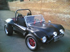
 ide height was fantastic it stuck the front on the deck and the arse of the car in the air. I would not be able to judge how height this would be until my engine was refitted.
I started to paint one half of the chassis in Hamerite hammered paint. This painted over top of the boat paint . The body prep would be put on hold until the chassis was completely painted. I hoped the temperatures would have improved outside by then. I was going to spray with a modern type of spray station and felt that it would be a good idea to spray a primer filer coat onto the body work to see how this sprayed.







 Posts
Posts


