10th November 2007
Whilst
acquiring bits for the turbo
accessory bits i needed I
acquired a Collins Group A -31 Actuator which was
supposed to be compatible with my T3 Turbo which came from a Ford
Cosworth lump.
I soon realised that my actuator had a straight arm. This was
annoying, as my bracket that came with my turbo positioned the actuator too high and looked as
if it required an arm with a bend in it. This was particularly odd as it was sold with a straight arm actuator fitted. I now believe the reason this worked before was that the compressor output on the side of the turbo must have been directed in another direction. Additionally you will notice that the actuator was second hand and someone has welded the nut onto the thread. This is supposed to be a locking nut so I could not imagine why this had been done. It was lucky I had a nut splitter. This made short work of the nut and it came off easily, otherwise I would have to locate a replacement.
I decided that as the turbo
components where able to get very hot that I would use stainless steel sheet to make the bracket. Luckily I have a scrap merchant that i have used for some years who is happy to sell me scrap stainless steel. Firstly I removed one of the compressor securing plates and drew around it on a
piece of card. I left a large area of card on the opposite side of this so that i could shape it into a bracket. I bolted on the card board and set the actuator where i wanted it to go. I bent the card back so that i could mark the position of the bolts that protrude from the actuator. This gave me a rough template for the compressor housing bolts and their relation to the actuator mountings. From this I was able to use the old bracket to transfer the other holes that the actuator uses.
I was then able to draw around the holes to make a bracket shape. This was

the stuck onto the stainless with paper glue.The
holes could then be drilled in the stainless where they where
marked on the paper template. Drilling this required a very slow drill speed as it is easy to break,blunt or snap a drill bit when drilling stainless. I

am pleased to say that my
Starrett 3/4" hole saw and
arbour drilled through the stainless also without any sign of problems.
The next job was to start cutting the the bracket out by cutting around the paper template. I used an angle grinder for this although a plasma cutter would have been faster. You must remember to keep the template wet otherwise it will burn from the heat of the cutting process.
Once the template had been roughly cut around I used a clamp and a large 4x4 post to clamp it to so that it could be worked on. The metal was soon removed fr

om around the template by filing it away with a coarse metal work file. Once the bracket had been c

leaned up it could be bent to shape. This required a large vice and a larger hammer. Bending metal always leaves small marks on the metal and I used a sanding disc in the angle grinder to clean them off. Warning Don't pick the bracket up after sanding, It gets very hot.
The bracket was fitted to the turbo to see if the angles to which the bracket had been bent where suitable for the actuator to
fit and reach the waste gate crank without bending the arm in the actuator head. The first trial showed that the bracket was still about 10
degrees out.
Once the bracket had been re-bent it was fitted onto the
tu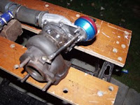 rbo
rbo to check everything fitted
OK. The sanding process leaves striation lines on the surface of the stainless. I used some copper saucepan
base cleaner to remove this giving a better finish to the metal work.
The Actuator fitted onto the turbo quite nicely and when making the
bracket I had made sure that the bracket would not foul anything else. Especially as the oil return was quite close to the bracket.
You can see in the picture above I have replaced the compressor bolts with
Allen bolts and sealed the water unions with 18mm x1.5mm pitch
Allen grub screws.
 This was the first attempt , the second was no nearer. It was time to change the company i was using to make it. Stainless is obviously slippery to weld.


