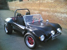
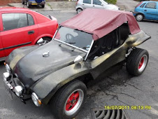
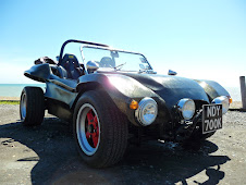
 After modifying the bodywork of the car during the installation of the IRS components in preparation for allowing the A-arms to rise and have enough clearance I had decided to cut the body work high enough for the CSP bars to fit. The main reason for this was I was trying to stiffen up the rear suspension. The IRS fitting process meant that the Frame Horns had to be heated an bent to accomodate the drive shafts. This took some strength out of the Frame Horns and the CSP Torque kit would imrove this ensuring the floating Frame horns where locked into the rest of the chassis.
I had detailed the body work that needed cutting in a previous article and will not cover it again in this article. The main reason for the body removal was to eliminate a portion of the tyre well that came into the area the CSB Torque bars will fit into. This problem is only associated with my style of fibreglass bodywork and is not neccessary if you are using the standard beetle body.
After cutting the body work down I found that it was very difficult to get hold of the CSP Torque Bar kit. I did not want to import a new one from CSP as this was quite expensive and had luckily found one on eBay only to find that the seller was not really interested in selling it and was wasting every ones time by shilling the bids at the last moment so unfortunately I had to let that one go. A month later I had been watching eBay and all of the usual sale sites for some time when I saw the CSP
 kit above advertised. I secured it along with the rear gearbox mount. It was in excellent condition and all the welding work had been done and the mounting plates had been anodised in a gold zinc coating. This did not appear to be paint so I presumed it must have been plated.
The installation of this Torque bar kit is fairly straight forward the welding that is usually needed for this installation is detailed here: http://www.csp-shop.de/technik/pdf/deeng/20917.pdf You can see that the three bars triangulate the frame horns which support the gearbox cradle significantly reducing the flex that gets put into them from a high performance engine. The bars being made from Aircraft grade aluminium make the adjustable bars are very strong.
 The rear cradle that supports the engine and gearbox is securely bolted to the frame horns by two large 36mm fine threaded bolts. They can really only be got at easily with the engine removed from the car. Considering this is a simple process of disconnecting the throttle cable and then undoing the four bolts, this is where we will start in my installation of the welded torque bar.
With the engine bolts removed and the throttle released the engine will sit on a jack above a plank of wood. This will hold the engine whilst it is still located on the final gearbox drive shaft. Be advised it safer for two people to help removing the engine. The engine can be slowly drawn and wiggled backwards off the final drive shaft in the gearbox until it becomes disengaged. The engine will then be solely supported by the jack and it should be slowly lowered to the ground with the engine nearer the ground. Ask your friend who has been helping you stabilise the engine on the way down to help you lift it from the jack onto another plank of wood. This should be easily accomplished but ensure if you are following this that you use the proper lifting techniques so not to strain your back. The engine long block should now be removed exposing the gearbox.
The gearbox is mounted between the rear frame horns inside the bell housing at the bottom where it meets the cradle there are two bolts that hold the gearbox rubber mounts to the gearbox. Undo these and secure the bolts and washers for later use.You will now need to place a jack under your gearbox to support it . Again place a piece of wood between the gearbox and jack to prevent damage. Ensure the jack is biased towards the rear of the gearbox near the bell housing . With the jack in position you will need to remove the lower rubber gearbox mounts on one side of the gearbox. This will allow the gearbox to be lifted out. Use the jack to raise the gearbox out of its cradle.
The gearbox should now be disconnected from the cradle and the cradle can be removed by undoing the two large 36mm bolts that hold it onto the frame horns. You will need considerable force to undo these bolts. Use penetrating fluid like plus gas to soak the bolts for a few hours before you proceed. If your lock the you will already have a long bar that you can use as an extension to your socket set . you will need at least three foot or a metre of something like scaffold pole or if tour lucky an air powered impact wrench. With the cradle free from the frame horns you can start re-assembly with the new cradle. Ensure that you re grease both the threads in the frame horns before you bolt on the cradle. If you had your torque kit bought as a kit that you can assemble You will have two holes on each side of the cradle that take the mounts for the diagonals. These bolt on with the Allen bolts supplied. If you are having to make your mounts follow the CSP article to locate them in the correct axis. Replacing the gearbox into the cradle is the reverse of the removal process. You can bolt one or both of the rubber gearbox mounts on the side(s) of the bell housing. Then lower the gearbox back onto the new cradle.
The top mounts for the Torque bar are located of the suspension damper arm. To fit them you must removed the top damper mount. To access this you will find it easier to remove the wheel on the side you are working on. With the first wheel removed you should easily be able to find the damper and the retaining bolt at the top. The suspension system is under load and although you can remove the nut from the bolt you will not be able to remove the bolt without remove in the load from the torsion bars that is applied to the swing arm. You can buy a tool from VW heritage to pull the spring plate upwards although this is fairly expensive and is not used very often. I have found that you can use good quality luggage straps to do the same job. The luggage straps have locks on them that allow you to wind up the strap under load. If you are buying these get ones bigger than an inch in size with metal buckles. Loop the strap over the arm and back around the spring plate you should be able to ratchet the strap up to pull the spring plate up. You only need to achieve a few mm as this will allow the top damper bolt to be able to be slid out and the new longer one slid in its place. The damper can then be slid back onto the new bolt. The top mount can then be slid onto the bolt and the whole assembly can be bolted up. If you are not using prewelded assemblies then you will have to just pop on the bushing and follow the CSP installation instructions to weld the mounting tabs in the correct axis. This can then be repeated for both sides. It is easier to hold the car on axle stands whilst you are removing the wheels this allows you to remove both wheels and work without having to put on a wheel and then jack up and remove the other. With the mounts in place the bars can be attached using the supplied Allen bolts . Beware if you have wound out the threads on the bars that these are handed and are not reversible.


