Search This Blog

Redline Linkage Saga

Wednesday July 2005
My Redline Linkage kit was on order from Weber I was excited about receiving the new one as the old linkage kit transversed the floor of the engine compartment. This used a poor bolting system to bolt a vertically mounted bearing. Pulling on the throttle would pull the vertical bearing over making the accelerator stay depressed. Clearly this was a poor design and the Redline one transversing across the carburettors was much easier to set up.

The kit I had purchase came with the manifolds as part of the kit so I removed my manifolds that where short and touched the exhaust and replaced them with the Redline ones ensuring that the gaskets where seated well. I replaced the carburettors ensuring that the gaskets where oiled before the carburetors where seated onto the manifolds. The linkage kit was next and the top bar went on easily. However for some reason the linkage kit was too long to fit.

In error I tried to shorten them believing I could re tap the threads. This in theory was not so bad if I had picked the correct end to shorten. Opposing ends of the bar had left and right wound threads so that you could twist the rods to increase or decrease the bars length. I picked the left hand thread to shorten and only had a right hand tap to re- thread. As you can imagine this did not work at all and left me with a problem . My new linkage kit was lacking a vital part.

As luck would have it I searched Yell for a company that produced these ball joint kits. I found a company that produced them in my locale and telephoned them. They had moved north , but where still willing to help supplying me with lockable ball joints that could be removed whilst in situ. I was fortunate as this error cost me only £30. An new linkage kit would have been much more expensive.

The lockable ball joints turned up two days later they where exactly the correct length and with the quick release system fitted in about 2 minutes by removing the little wire and swinging it out and removing it to release the ball. The difference was amazing they took up all the slack in the system and allowed the linkage kit to be calibrated evenly.

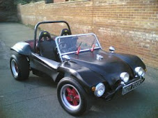
The engine was turned over it started and the engine ran beautifully. I wondered what the chassis /engine ran like. Several moments later I figured out that the engine could be started with a hot wire and the steering could be fitted to give some ability to steer the chassis. This coupled with a lawn mower petrol tank we where using and a child's car seat. The Chassis was finished and mobile! The chassis was very light and with no weight in the front the 100ft drive way was used most of the rest of the sunny afternoon driving backwards and forwards up and down the drive. This was the first real time test of all the components on the chassis. The braking component worked fine in fact the front was so good it seemed to lock up easily. The engine provided so much power it was easily able to push the front wheels off the ground. By the end of the day I was smiling from head to toe and covered by a huge grin. I was amazed that the project was looking so good. I had finished prepping the chassis and was trialing fitting of components in the tub prior to a quick respray.

The Texas Connection

With the bodywork alterations and preparation well under way I was looking on EBay for a twin carburettor system that would fit on the buggies engine. The single draft 40mm Weber that was fitted just did not have the performance that I required from the buggy. I decided that I could sell the manifold and carburettor on eBay and raise about £100-£150 towards the cost and was hoping as I had been watching the prices of the twin Weber IDF 40 systems go up and up as they where selling for about£600.00 at that time that I would be able to find one that was suitable for the 1600 VW flat four engine. I hoped there was as I new from research that the addition of two carburettors to the engine would provide a better performance. I checked and double-checked the information needed to jet them:


The 40IDF sizes required for the carburetters where:
Venturi: 28mm
Main Gas: 1.30
Main A/C: 2.00
Emulsion Tube: F11
Idle jet: 0.55
Pump Jet: 50.

Armed with this information I was able to look for my Carburettors. After some time a match came up but it was not in England it was in Kentucky, Texas. I placed several bids on the carburetors, manifold and linkage kit. The auction eventually ended and I had won them. They took nearly two weeks to arrive and where not delivered to my house because of customs duty. There was approximately £80 of duty that needed to be paid on pick up of them. Even so this was not bad, as the carburetors had cost me £555.00 in total.

The day the carburetters arrived I was happily installing them after cleaning them thoroughly with carb cleaner. The engine would not start and the accelerator pump gaskets where leaking badly. I contacted the Weber dealer in my area and arrange for two new accelerator pump diaphragms to be sent to me by next day delivery.

The new accelerator pump diaphragms arrived the next day and I oiled the diaphragms and placed them in each of the carburettors. This stopped the pumps from leaking and the engine would run only if you pumped the accelerator. I had a blockage somewhere in the main jets.

Luckily I found an article on http://www.superbeetles.com/performance101/jun.htm
that talked about setting up Weber carburetors. After reading this and the following article:
http://www.superbeetles.com/performance101/jul.htm . The articles where very interesting as they talked you through setting up the carburettors.

After following the articles I was ready to try again and installed the carburettors onto the manifolds. This time I had also replaced the manifolds oiling the gaskets at all the joins. There was no improvement and I was very puzzled. I took the Carburettors off and took them to a friend who was also a performance car mechanic. He said that the carburettors typically Weber's had very small ventri in the body work of the carburetor and sometimes these get blocked. A week later and 4 tins of Carb cleaner he brought them back and I re-installed them. They fired up beautifully and the engine ticked over.

It was soon noticeable that the carbs where sitting almost on the exhausts. This was potentially boiling the fuel in the Carburetors. The only option was to purchase the Redline Weber linkage kit and manifold kit.

Body Check

Friday.
The first trial of the body fitment onto the chassis came as a bit of a relief, time for a beer and to see what the buggy would look like with the new wheels. The bonnet petrol fuel position had been altered so that it was in the middle of the bonnet.

The trials of the previous weeks had begun to show some clearer images of what the buggy was going to look like. What my partner Catherine had seen several weeks before in my garage was starting to take shape and for the first time everything was steaming ahead.

The body work holes where drilled through the chassis to provide bolt holes with which to bolt the body onto the chassis. The original channel washers where cleaned and painted and used on top of the fibreglass and a 8mm stainless bolt with nyloc nuts.

It was time to start looking at cleaning down the paint from the body work and the interior components like the dash board, bumpers and roll bar.

Body Alteration part two.

Whilst altering the back transom of the tub for height. It became apparent that the middle of the front bulk head needed to be brought forward so that it sat on the rubber gasket properly.

You can see from the picture that most of the perimeter bolt down area was also needing some repair work and this was all repaired at the same time.

The picture also shows the tank in position with its newly welded intake. Luckily the tank was bone dry as it had been in the garage for more than ten years. Normally you should take precautions when welding a tank , but in this instance the welding was quite straightforward.

The front bulkhead lip was cleaned up and taken back to the fibreglass by 160 grit disk on an angle grinder and some was removed by a Dremel type tool. The area was cleaned with cellulose and then the front lip of the bulk head was brought back to size by strapping a steel former below the lip. This allowed the fibreglass to be layered on top of the wax coated steel. The repair was then completed again on the reverse side. material was cut away and then fibre glassed to provide a solid base. During the fitting of the body A replacement master cylinder had been purchased with a new brake fluid reservoir. The brake fluid reservoir chamber unfortunately hit the bulkhead and you could not unscrew the lid.


I decided to construct a block of wood in the shape of the reverse of the lid area to be able to undo the brake fluid reservoir lid. I cut a hole the same size as this former in the bulkhead and then covered the former with wax . It could then be pushed through the bulkhead and produce a blank that the fibre glass could be applied over which would then take the shape of the block.

Once the fibreglass was semi dry I was able to remove the former and it left a nice square box around the brake fluid reservoir. The other side of the bulkhead was ground and then cleaned and it was then fibre glassed to make a strong solid join.

During the course of the alterations I placed a bid on some Revolution wheels that's where for sale on eBay. I new they were in London so could be picked up and just needed to win the auction for them.

I had decided that the original bonnet position for the petrol tank filler was wrong as it was more traditional to have this placed in the middle of the tank and I had already welded the tank inlet to accommodate this. I firstly made a metal sheet that would fit over the old hole. I drilled three bolts through the bonnet and the sheet so that it could be bolted on. Prior to bolting it on the sheet was covered with wax so that it could be released after the fibreglass had been applied. I also ground out the area around the hole so that the edge of the whole had a slant . The fibreglass was then able to be applied on one side. I removed the bolts when it had semi hardened and increased the area of fibre glass layering. The other side was then fibre glassed and then sanded to a fine finish.

The repair work needed on the engine cover and number plate apron was achieved in a similar process. The area was cut back and ground down at the edges to chamfer them. The metal sheet was waxed and clamped in position . The front surface was then filled with fibreglass. The whole tub was turned over the sheet removed and the back of the area strengthened by long sheets of fibreglass. Over the course of the week several other areas where repaired in a similar method. The fit to the chassis was checked at each change to ensure nothing that had been done would stop the tub from fitting precisely on the chassis.

Body Alteration part one.

A week later.
With the wooden blocks screwed in place i could gauge the profile that i needed to make to fit this section onto the chassis. Several trial fits of the tub onto the chassis had been made to check that the tub fitted evenly on the chassis base.

I made cardboard templates of the profile that could be used to check the height of the build up of fibreglass. I intended to use a vernier type gauge to ensure that the build up of fibreglass matched the distances that I could measure on the cardboard profile this giving me an accurate indicator. The reason for this process was that laying down fibreglass over a large area meant that long lengths of fibreglass sheeting needed and the wooden blocks had to be removed before any fibreglass could be laid.

The wooden blocks were removed and the surface was cleaned up with the 160 grit sanding angle grinder disk. After final preparation with the cellulose thinners. I was able to start fibre glassing. It was soon clear that my guess at the amount of fibreglass was sadly under estimated.

A week later and with Ben now turning up regularly to help with mixing of resin material the transom was building up slowly. I had not anticipated that the fibre glassing would over spill the area. This amazingly was a helpful thing, it gave strength to the new material as it was talking on the contour of the body work and by encroaching forward past the transom it meant I could cut back the material to provide a clean profile in the inside of the tub. The benefit of this was that I could ensure the integrity of the fibre glassing was good. The picture on the right shows the material cut back. I found that an angle grinder was the only way the material could be cut it was amazingly hard. I estimated the amount of fibreglass used at £300.00 which meant in reality buying a second hand shell was more expensive to build as a restoration than buying a new one. This was not something that did not bother me as by then I had found out that FibreFab had stopped making the SWB Rat and where no longer in the United Kingdom in Wokingham. I was restoring a classic beach buggy that there were few examples off left running. Additionally I drew energy from my fathers illness I now had a mission: " To take my father for a ride in the car that we started building together more than 20 years previously".

Body preparation and shell restoration

The next couple of weeks
In the next couple of weeks I assessed the work and decided in which order my time should be spent. Ten years prior to this I had had the opportunity to work with fibreglass repairing canoes as a project with the school. Although this was useful, it was no way going to prepare me for the amount of fibre glassing that was ahead.

You can see from the picture opposite the holes in the rear seat area where fairly large and looked structural.

The bodywork did not fit on the chassis as the sides of the fibreglass had seemed to have warped. These holes would have to be re fibre glassed and special attention would need to ensure that the new fibreglass did not encroach or hit the chassis. There where two additional holes at the corner of the tub across from the rear transom, these would need fibre glassing and would be quite difficult as they were on a corner. I decided to start with the easiest piece. I went to a local car accessory company and bought £50 of glass, resin and hardener. My Angle grinder game out of my toolbox with a 180 grit sanding disk on it made light work of the paint and talking me down to the fibreglass surface easily. Additionally I located a 5L can of Cellulose in the back of the garage. A friend suggested this as a cleaning agent and with experimentation I found that the cellulose would make the fibreglass sticky thus enhancing the new fibreglass's ability to get a good contact. The fibre glassing was going well access to the web was providing additional information about cutting in the new glass to the old by cutting a slope on the join. Before long I had built a box section up and filled the hole in the other side. The box section was built up slowly in layers . The trick seemed to be in getting the first layer of fibreglass in place and semi -hard. The best way of achieving this seemed to be by using a former made from steel sheeting and using household Libron wax polish to act as a greasing agent. Luckily I choose a wax polish that was removable by the cellulose, this meant it was easy to clean down before the next layer was attached. I was almost ready for a first fit but I needed to know whether the new fibreglass work would hit any of the chassis members. It was time to ask my friend Ben to give me a hand to lift the body work back onto the chassis. I had made the battery area larger than it was originally as I wanted to place a bigger battery on board. Unfortunately I had not checked the larger area would fit in the hole in the between the chassis parts. It seemed as if the battery compartment had been designed small for a specific purpose. I had to cut the box section down so that it would fit between the chassis members. With the shape established and completed . My attention turned to the problem of the chassis not fitting the tub. There was about 2" of air between the chassis and the tub, this was marked out on the rear transom with wooden blocks so that the height could be gauged and a fit to the chassis could be made with the wooden blocks acting as a height adjustment for where the fibreglass should be. This fitting process allowed me to gauge the exact amount of fibreglass that was required. I needed to and purchase some more fibre glass as I new that I would need about £200.00 of fibreglass buying it from the auto shop. Fortunately my friend Ben was starting to visit on a regular basis and had helped a few times mixing up fibreglass for me. This was to become a vital part of the next stage of the body preparation as 2" of fibreglass vertically seemed to be an astronomical task. My partner Catherine partner was as usual confident that this was achievable. I was not so sure but I was going to give it my best shot.