12th December 2008.
Christmas and the bad weather that usually comes with it is arriving fast. This year I have managed to do a lot of work to my FibreFab SWB Rat. I have changed the rear suspension substantially to an IRS type that places the rear wheels firmly on the ground. This has improved the grip of the rear wheels and the buggy now feels like its running on rails. I have also managed to fit a rear disk conversion that has increased the stopping performance of the car. Unfortunately this year has brought a lot of engine problems that have made me fit a surrogate engine into the car whilst I build a new engine. This has been further troubled by finding someone who can line bore my new case ready for a new high performance crankshaft. I have now found a company that can line bore the case and they are based in Biggin Hill :
Baldyne Aviation Traders Engineer
Site 500, Biggin Hill Civil Airport, Biggin Hill,
Westerham, Kent TN16 3BN
Tel: 01959 540205
Classification: Car Engine Tuning & Conversion
They have assured me that they can still do the engine line boring and I am hoping to get the case to them in early January as I am committed to building my new engine next year after the Christmas and New Year fever has dissipated.
I want to finish wishing my readers a very happy Christmas and a happy New Year.
Installing a CSP Torque bar
31st October 2008
 After modifying the bodywork of the car during the installation of the IRS components in preparation for allowing the A-arms to rise and have enough clearance I had decided to cut the body work high enough for the CSP bars to fit. The main reason for this was I was trying to stiffen up the rear suspension. The IRS fitting process meant that the Frame Horns had to be heated an bent to accomodate the drive shafts. This took some strength out of the Frame Horns and the CSP Torque kit would imrove this ensuring the floating Frame horns where locked into the rest of the chassis.
I had detailed the body work that needed cutting in a previous article and will not cover it again in this article. The main reason for the body removal was to eliminate a portion of the tyre well that came into the area the CSB Torque bars will fit into. This problem is only associated with my style of fibreglass bodywork and is not neccessary if you are using the standard beetle body.
After cutting the body work down I found that it was very difficult to get hold of the CSP Torque Bar kit. I did not want to import a new one from CSP as this was quite expensive and had luckily found one on eBay only to find that the seller was not really interested in selling it and was wasting every ones time by shilling the bids at the last moment so unfortunately I had to let that one go. A month later I had been watching eBay and all of the usual sale sites for some time when I saw the CSP kit above advertised. I secured it along with the rear gearbox mount. It was in excellent condition and all the welding work had been done and the mounting plates had been anodised in a gold zinc coating. This did not appear to be paint so I presumed it must have been plated.
The installation of this Torque bar kit is fairly straight forward the welding that is usually needed for this installation is detailed here: http://www.csp-shop.de/technik/pdf/deeng/20917.pdf You can see that the three bars triangulate the frame horns which support the gearbox cradle significantly reducing the flex that gets put into them from a high performance engine. The bars being made from Aircraft grade aluminium make the adjustable bars are very strong.
 The rear cradle that supports the engine and gearbox is securely bolted to the frame horns by two large 36mm fine threaded bolts. They can really only be got at easily with the engine removed from the car. Considering this is a simple process of disconnecting the throttle cable and then undoing the four bolts, this is where we will start in my installation of the welded torque bar.
With the engine bolts removed and the throttle released the engine will sit on a jack above a plank of wood. This will hold the engine whilst it is still located on the final gearbox drive shaft. Be advised it safer for two people to help removing the engine. The engine can be slowly drawn and wiggled backwards off the final drive shaft in the gearbox until it becomes disengaged. The engine will then be solely supported by the jack and it should be slowly lowered to the ground with the engine nearer the ground. Ask your friend who has been helping you stabilise the engine on the way down to help you lift it from the jack onto another plank of wood. This should be easily accomplished but ensure if you are following this that you use the proper lifting techniques so not to strain your back. The engine long block should now be removed exposing the gearbox.
The gearbox is mounted between the rear frame horns inside the bell housing at the bottom where it meets the cradle there are two bolts that hold the gearbox rubber mounts to the gearbox. Undo these and secure the bolts and washers for later use.You will now need to place a jack under your gearbox to support it . Again place a piece of wood between the gearbox and jack to prevent damage. Ensure the jack is biased towards the rear of the gearbox near the bell housing . With the jack in position you will need to remove the lower rubber gearbox mounts on one side of the gearbox. This will allow the gearbox to be lifted out. Use the jack to raise the gearbox out of its cradle.
The gearbox should now be disconnected from the cradle and the cradle can be removed by undoing the two large 36mm bolts that hold it onto the frame horns. You will need considerable force to undo these bolts. Use penetrating fluid like plus gas to soak the bolts for a few hours before you proceed. If your lock the you will already have a long bar that you can use as an extension to your socket set . you will need at least three foot or a metre of something like scaffold pole or if tour lucky an air powered impact wrench. With the cradle free from the frame horns you can start re-assembly with the new cradle. Ensure that you re grease both the threads in the frame horns before you bolt on the cradle. If you had your torque kit bought as a kit that you can assemble You will have two holes on each side of the cradle that take the mounts for the diagonals. These bolt on with the Allen bolts supplied. If you are having to make your mounts follow the CSP article to locate them in the correct axis. Replacing the gearbox into the cradle is the reverse of the removal process. You can bolt one or both of the rubber gearbox mounts on the side(s) of the bell housing. Then lower the gearbox back onto the new cradle.
The top mounts for the Torque bar are located of the suspension damper arm. To fit them you must removed the top damper mount. To access this you will find it easier to remove the wheel on the side you are working on. With the first wheel removed you should easily be able to find the damper and the retaining bolt at the top. The suspension system is under load and although you can remove the nut from the bolt you will not be able to remove the bolt without remove in the load from the torsion bars that is applied to the swing arm. You can buy a tool from VW heritage to pull the spring plate upwards although this is fairly expensive and is not used very often. I have found that you can use good quality luggage straps to do the same job. The luggage straps have locks on them that allow you to wind up the strap under load. If you are buying these get ones bigger than an inch in size with metal buckles. Loop the strap over the arm and back around the spring plate you should be able to ratchet the strap up to pull the spring plate up. You only need to achieve a few mm as this will allow the top damper bolt to be able to be slid out and the new longer one slid in its place. The damper can then be slid back onto the new bolt. The top mount can then be slid onto the bolt and the whole assembly can be bolted up. If you are not using prewelded assemblies then you will have to just pop on the bushing and follow the CSP installation instructions to weld the mounting tabs in the correct axis. This can then be repeated for both sides. It is easier to hold the car on axle stands whilst you are removing the wheels this allows you to remove both wheels and work without having to put on a wheel and then jack up and remove the other. With the mounts in place the bars can be attached using the supplied Allen bolts . Beware if you have wound out the threads on the bars that these are handed and are not reversible.
 After modifying the bodywork of the car during the installation of the IRS components in preparation for allowing the A-arms to rise and have enough clearance I had decided to cut the body work high enough for the CSP bars to fit. The main reason for this was I was trying to stiffen up the rear suspension. The IRS fitting process meant that the Frame Horns had to be heated an bent to accomodate the drive shafts. This took some strength out of the Frame Horns and the CSP Torque kit would imrove this ensuring the floating Frame horns where locked into the rest of the chassis.
I had detailed the body work that needed cutting in a previous article and will not cover it again in this article. The main reason for the body removal was to eliminate a portion of the tyre well that came into the area the CSB Torque bars will fit into. This problem is only associated with my style of fibreglass bodywork and is not neccessary if you are using the standard beetle body.
After cutting the body work down I found that it was very difficult to get hold of the CSP Torque Bar kit. I did not want to import a new one from CSP as this was quite expensive and had luckily found one on eBay only to find that the seller was not really interested in selling it and was wasting every ones time by shilling the bids at the last moment so unfortunately I had to let that one go. A month later I had been watching eBay and all of the usual sale sites for some time when I saw the CSP
 kit above advertised. I secured it along with the rear gearbox mount. It was in excellent condition and all the welding work had been done and the mounting plates had been anodised in a gold zinc coating. This did not appear to be paint so I presumed it must have been plated.
The installation of this Torque bar kit is fairly straight forward the welding that is usually needed for this installation is detailed here: http://www.csp-shop.de/technik/pdf/deeng/20917.pdf You can see that the three bars triangulate the frame horns which support the gearbox cradle significantly reducing the flex that gets put into them from a high performance engine. The bars being made from Aircraft grade aluminium make the adjustable bars are very strong.
 The rear cradle that supports the engine and gearbox is securely bolted to the frame horns by two large 36mm fine threaded bolts. They can really only be got at easily with the engine removed from the car. Considering this is a simple process of disconnecting the throttle cable and then undoing the four bolts, this is where we will start in my installation of the welded torque bar.
With the engine bolts removed and the throttle released the engine will sit on a jack above a plank of wood. This will hold the engine whilst it is still located on the final gearbox drive shaft. Be advised it safer for two people to help removing the engine. The engine can be slowly drawn and wiggled backwards off the final drive shaft in the gearbox until it becomes disengaged. The engine will then be solely supported by the jack and it should be slowly lowered to the ground with the engine nearer the ground. Ask your friend who has been helping you stabilise the engine on the way down to help you lift it from the jack onto another plank of wood. This should be easily accomplished but ensure if you are following this that you use the proper lifting techniques so not to strain your back. The engine long block should now be removed exposing the gearbox.
The gearbox is mounted between the rear frame horns inside the bell housing at the bottom where it meets the cradle there are two bolts that hold the gearbox rubber mounts to the gearbox. Undo these and secure the bolts and washers for later use.You will now need to place a jack under your gearbox to support it . Again place a piece of wood between the gearbox and jack to prevent damage. Ensure the jack is biased towards the rear of the gearbox near the bell housing . With the jack in position you will need to remove the lower rubber gearbox mounts on one side of the gearbox. This will allow the gearbox to be lifted out. Use the jack to raise the gearbox out of its cradle.
The gearbox should now be disconnected from the cradle and the cradle can be removed by undoing the two large 36mm bolts that hold it onto the frame horns. You will need considerable force to undo these bolts. Use penetrating fluid like plus gas to soak the bolts for a few hours before you proceed. If your lock the you will already have a long bar that you can use as an extension to your socket set . you will need at least three foot or a metre of something like scaffold pole or if tour lucky an air powered impact wrench. With the cradle free from the frame horns you can start re-assembly with the new cradle. Ensure that you re grease both the threads in the frame horns before you bolt on the cradle. If you had your torque kit bought as a kit that you can assemble You will have two holes on each side of the cradle that take the mounts for the diagonals. These bolt on with the Allen bolts supplied. If you are having to make your mounts follow the CSP article to locate them in the correct axis. Replacing the gearbox into the cradle is the reverse of the removal process. You can bolt one or both of the rubber gearbox mounts on the side(s) of the bell housing. Then lower the gearbox back onto the new cradle.
The top mounts for the Torque bar are located of the suspension damper arm. To fit them you must removed the top damper mount. To access this you will find it easier to remove the wheel on the side you are working on. With the first wheel removed you should easily be able to find the damper and the retaining bolt at the top. The suspension system is under load and although you can remove the nut from the bolt you will not be able to remove the bolt without remove in the load from the torsion bars that is applied to the swing arm. You can buy a tool from VW heritage to pull the spring plate upwards although this is fairly expensive and is not used very often. I have found that you can use good quality luggage straps to do the same job. The luggage straps have locks on them that allow you to wind up the strap under load. If you are buying these get ones bigger than an inch in size with metal buckles. Loop the strap over the arm and back around the spring plate you should be able to ratchet the strap up to pull the spring plate up. You only need to achieve a few mm as this will allow the top damper bolt to be able to be slid out and the new longer one slid in its place. The damper can then be slid back onto the new bolt. The top mount can then be slid onto the bolt and the whole assembly can be bolted up. If you are not using prewelded assemblies then you will have to just pop on the bushing and follow the CSP installation instructions to weld the mounting tabs in the correct axis. This can then be repeated for both sides. It is easier to hold the car on axle stands whilst you are removing the wheels this allows you to remove both wheels and work without having to put on a wheel and then jack up and remove the other. With the mounts in place the bars can be attached using the supplied Allen bolts . Beware if you have wound out the threads on the bars that these are handed and are not reversible.
Engine Overhaul - replacement crank case
1st October 2008.
 After reeling from my engine case problems which occured when I was overhauling the original engine crankcase. I soon realised that there really was no way that the existing case could have been bored out to 94mm to accept the new barrels and pistons I had purchased. The main reason for this was that the 1300 box used adapters to hold the 8mm heads into the crankcase These adapters are know as case savers and where fitted to the later engines. These would have not allowed the cylinders to be bored out without cutting into these threads. This would therefore have not worked. Fortunately my original case had developed problems when I taped the oil gantries out to take the brass plugs. One of the 1/8NPT plugs under the fly wheel had split the case rendering it unusable. I am presuming that there was a fracture in the case prior to me cutting the thread that had spit when I used the extracter to remove the brass plug.
I managed to find a replacement crankcase on VZi from a gentleman in the other side of Brighton. Luckily the new crank case had been bored out to 94mm already and was already machined for full flow oil. The full flow oil process requires that the outlet of the oil pump be threaded and a plug screwed in and the main oil return be taped with a 3/8NPT tap. Generally speaking the new case was in good condition and had never been line bored as it was 64mm on the main bearings.
I decided that as i did not know the condition of the oil gantries that i would have to tap them. I started by removing the pressure valves. These are located on the bottom of the case at the front and back of the engine. The pressure valves and springs are covered by a screw in plug that has a large screw driver slot in its top. The easiest way to get these undone is to tap the right side of the slot with a screw driver and hammer , so using them as a punch to knock the cap undone. With the caps removed the springs can be removed giving access to the pistons. These are usually pressed tight up into the engine. I use a piece of cane that I cut down to gain the correct width to just fit into the piston. Once you have the right diameter you can knock this into the piston so that you can twist the piston out and ease the cane and piston out.
The gantry caps could then be removed from the case. I used a 1/8 drill to drill the centre of the caps and a wood screw turned into the cap until it was firm enough to allow a claw hammer to pull the screw and the cap out together. The exposed gantries could then be drilled and taped with their respective threads 1/8NPT, 1/4NPT and 3/8NPT. There are four 1/8NPT holes that need to be drilled out to 11/32". The two 1/4NPT threads can be taped straight into the gantry as the hole is already the correct size. The two 38NPT threads require the gantry hole to be drilled out to 9/16" before they can be taped. Generally speaking you need to drill the hole a bot longer than the length of your plug. I found that when taping the threads it was better to start the thread with a taper tap. I cut down a second taper tap to make a plug that was the same length of the screw plug that I was using. With the used together I was able to get the plugs to seat below the level of the casing.
Once I had taped and cleaned out the gantries I decided I would like to get the case media blasted to bring back its surface to look like new.
I also found out via a friend that as I was building a large engine I would probably be best to locate a new balanced forged crankshaft although I hadnt figured this into my budget I new that if my existing crank failed it would damage all the other components around it and so was really not worth the risk.
 After reeling from my engine case problems which occured when I was overhauling the original engine crankcase. I soon realised that there really was no way that the existing case could have been bored out to 94mm to accept the new barrels and pistons I had purchased. The main reason for this was that the 1300 box used adapters to hold the 8mm heads into the crankcase These adapters are know as case savers and where fitted to the later engines. These would have not allowed the cylinders to be bored out without cutting into these threads. This would therefore have not worked. Fortunately my original case had developed problems when I taped the oil gantries out to take the brass plugs. One of the 1/8NPT plugs under the fly wheel had split the case rendering it unusable. I am presuming that there was a fracture in the case prior to me cutting the thread that had spit when I used the extracter to remove the brass plug.
I managed to find a replacement crankcase on VZi from a gentleman in the other side of Brighton. Luckily the new crank case had been bored out to 94mm already and was already machined for full flow oil. The full flow oil process requires that the outlet of the oil pump be threaded and a plug screwed in and the main oil return be taped with a 3/8NPT tap. Generally speaking the new case was in good condition and had never been line bored as it was 64mm on the main bearings.
I decided that as i did not know the condition of the oil gantries that i would have to tap them. I started by removing the pressure valves. These are located on the bottom of the case at the front and back of the engine. The pressure valves and springs are covered by a screw in plug that has a large screw driver slot in its top. The easiest way to get these undone is to tap the right side of the slot with a screw driver and hammer , so using them as a punch to knock the cap undone. With the caps removed the springs can be removed giving access to the pistons. These are usually pressed tight up into the engine. I use a piece of cane that I cut down to gain the correct width to just fit into the piston. Once you have the right diameter you can knock this into the piston so that you can twist the piston out and ease the cane and piston out.
The gantry caps could then be removed from the case. I used a 1/8 drill to drill the centre of the caps and a wood screw turned into the cap until it was firm enough to
 allow a claw hammer to pull the screw and the cap out together. The exposed gantries could then be drilled and taped with their respective threads 1/8NPT, 1/4NPT and 3/8NPT. There are four 1/8NPT holes that need to be drilled out to 11/32". The two 1/4NPT threads can be taped straight into the gantry as the hole is already the correct size. The two 38NPT threads require the gantry hole to be drilled out to 9/16" before they can be taped. Generally speaking you need to drill the hole a bot longer than the length of your plug. I found that when taping the threads it was better to start the thread with a taper tap. I cut down a second taper tap to make a plug that was the same length of the screw plug that I was using. With the used together I was able to get the plugs to seat below the level of the casing.
Once I had taped and cleaned out the gantries I decided I would like to get the case media blasted to bring back its surface to look like new.
I also found out via a friend that as I was building a large engine I would probably be best to locate a new balanced forged crankshaft although I hadnt figured this into my budget I new that if my existing crank failed it would damage all the other components around it and so was really not worth the risk.
IRS vs Swing Axle...
17th August 2008.
There seems to be a huge amount of debate on the web forums from www.Volkszone.co.uk to theSamba.com and even to Beachbuggy.org.uk on whether the retro fitting of an IRS conversion would benefit an old swing axle designed chassis. Before I can give you my thoughts on this I would like to show you the two pictures that I have of my buggy with first the Swing Axle rear end and then the retro fitted IRS conversion.
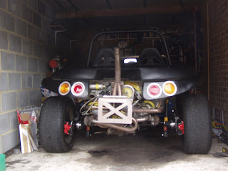

Initially there appears not to be much difference between the two designs although the angle that the photographs where taken at are not ideal.
With this in mind I will show you the two designs situated in the air with the wheels removed so that a closer look at the two designs can be seen.

 immediately you can see the difference between the two suspension types. The swing axle design places the wheels onto the ground at a slight angle causing only a partial part of the tyre to get the full weight of the vehicle in comparison the IRS suspension places the axle totally horizontal to the ground enabling all of the surface of the tyre to support the weight of the vehicle.
The main advantage of IRS here is that tyre wear is more even across the tyre. In addition because the full area of the tyre is carrying the weight of the vehicle the stability of the car is much improved when cornering and more traction is available at launch when starting from a stopped position. This all said the swing axle design also has some merits as its provides lower traction of the rear wheels making wheel spins easier and making the driver have more work to keep the rear from stepping out. These can also be seen as bad attributes but to be honest it really comes down to how you want the car to drive.
Personally I like a car to drive like its on rails as this means you can get the maximum amount of fun by traveling fast around corners.
My own IRS conversion is detailed here in six differant blogs starting from removal orf the swing axle gearbox and ending with fitting the A-Arms and spring plates. (Click on an image to goto that part please from one of the six shown below.)


Remember that the most important decision on your suspension depends on your engine performance and your driving style. With smaller wheels and tyres and narrower width there will be not so much tyre wear.
My engine rebuild has moved forward a little and it looks like I may have sourced a new crank case that has been pre bored out to 94mm. In the next episode find out if I managed to purchase it or if I am still looking for a replacement.
There seems to be a huge amount of debate on the web forums from www.Volkszone.co.uk to theSamba.com and even to Beachbuggy.org.uk on whether the retro fitting of an IRS conversion would benefit an old swing axle designed chassis. Before I can give you my thoughts on this I would like to show you the two pictures that I have of my buggy with first the Swing Axle rear end and then the retro fitted IRS conversion.


Initially there appears not to be much difference between the two designs although the angle that the photographs where taken at are not ideal.
With this in mind I will show you the two designs situated in the air with the wheels removed so that a closer look at the two designs can be seen.

 immediately you can see the difference between the two suspension types. The swing axle design places the wheels onto the ground at a slight angle causing only a partial part of the tyre to get the full weight of the vehicle in comparison the IRS suspension places the axle totally horizontal to the ground enabling all of the surface of the tyre to support the weight of the vehicle.
The main advantage of IRS here is that tyre wear is more even across the tyre. In addition because the full area of the tyre is carrying the weight of the vehicle the stability of the car is much improved when cornering and more traction is available at launch when starting from a stopped position. This all said the swing axle design also has some merits as its provides lower traction of the rear wheels making wheel spins easier and making the driver have more work to keep the rear from stepping out. These can also be seen as bad attributes but to be honest it really comes down to how you want the car to drive.
Personally I like a car to drive like its on rails as this means you can get the maximum amount of fun by traveling fast around corners.
My own IRS conversion is detailed here in six differant blogs starting from removal orf the swing axle gearbox and ending with fitting the A-Arms and spring plates. (Click on an image to goto that part please from one of the six shown below.)
Remember that the most important decision on your suspension depends on your engine performance and your driving style. With smaller wheels and tyres and narrower width there will be not so much tyre wear.
My engine rebuild has moved forward a little and it looks like I may have sourced a new crank case that has been pre bored out to 94mm. In the next episode find out if I managed to purchase it or if I am still looking for a replacement.
A new start and a true friendship
13th August 2008
 "When things get bad and you wonder what on earth you are doing . Sometimes a saint appears and gives you a differant solution....!"
With my crankcase cracked and my engine re-build put on hold. I was lucky enough to have a good friend step out and offer me a tempory solution. My friend John knowing my dilema offered me one of his engines to put in my car until I had researched and purchased the parts I needed to build a new engine that I had propossed to do. This was a gladly accepted gift as I could test out the disk conversion and IRS conversion that I had been working on for the past few months. Obviously without this engine It would be some time before I could have the new engine built up and runnning in the car.
I needed to use the clutch and cover plate from my old engine along with my distributor, HT leads and rocker arms. The engine was fitted into my buggy in an afternoon.
 With the engine fitted I new I would have to redesign the number plate fixing. I had previously wanted this
  to look good and to be made out of stainless steel , but as the buggy previously had a rear cage that still needed to be extended I felt it was a good time to redesign and make the mount i really wanted. The number plate body was made out of 5mm stainless. The holes where cut to help reduce the weight of the piece I made a mount that would take my existing stainless steel tube number plate lamp. The finished result looked very good and I was happy that I could still fabricate it after the problems I had had with the previous engine.
I had also been lucky enough to find a new crankcase on vzi and although it was a little expensive I was awaiting some photos.
Engine Overhaul - The break down
 25th July 2008
Readers of this blog are aware that I had a catastrophe that was caused by a small piece of bakerlite that sat under the fuel pump. Whilst servicing a crack in this item I managed to shear of the Bakelite and drop a small piece of it into the crankcase. This was disastrous as my engine had done less
 than 250 miles since its last rebuild and there was no way of retrieving it other than dismantling the engine. Firstly I must say a thanks to the informed members of VZI who stated not only where the parts would end up but where they would get mashed and what they would destroy if left in situe. To be quite frank they stated the exact position. The yellow arrow points to where the bits ended up. This is just under the timing gear on the camshaft. The green arrow shows the oil feed to the crankshaft. The red arrow shows the lower pump ring that the Bakelite pump bush fits into.
To be honest I am glad VZI exists. First drain the engine oil.
I stripped the engine down in a day removing the cylinder heads by removing the rocker covers , then the rocker shafts and then the eight nuts that hold each of the heads in place. With the heads
 removed the barrels could be removed taking special care to get them out so far that the gudgeon pins could be removed and the pistons removed still attached to the barrels. This is a little tricky but with a pair of long nose pliers to remove the circlips the pistons can be removed by sliding out the gudgeon pins. These can sometimes be a little st
 iff and a warm air blower like a paint stripper is enough to gently warm the piston to make the pin slide out again. With the pistons and barrels removed the main pulley can be undone at the front of the engine. If this is tight then the flywheel will need to be locked in position. Personally I tried to use a bar between two bolts and still resorted to buying the correct tool from eBay. This fits into the top engine bolt and securely holds the flywheel so that the front pulley and then flywheel nut can be undone. The short block is then able to be split. I removed the cylinder studs and the oil pump and the oil strainer first to allow better access to the case. There are eight large 17mm bolts and a large number of 13mm bolts around the case that all need to be undone. Make sure that you have got to all the 13mm bolts as there are some that are hidden tight against the back of the fly wheel and also in other hard to get to areas. With all the engine nuts undone . The case will still be stuck together. You will need a rubber mallet or a piece of wood and a hammer to carefully knock the case apart generally speaking its easier to lay the engine on a block of wood on its left hand side so the eight large studs are facing you. There are several good places around the case that you can hit , which will break the case seal. Once you have the case halves separated you can draw the top half on the engine case of the bottom. This will expose all of the internal workings of the engine so make sure you have a large quantity of rags or cloths that you can mop up the oil slick that comes out. Before going further you need to retrieve the cam followers that have fallen into the bottom case. You also need to check that you have two dots on the crankshaft camshaft timing gear and one on the camshaft gear. these are vital to lining up the engine timing, when the hole engine is put back together. Once this has been determined remove the camshaft and cam bearings and place them in a box. Carefully lift out the crankshaft with the con rods and put this in another box with some rags to soak up the oil. You need to ensure that you have all of the bearing halves out of the engine.
With the cases bare you can start to mop out the engine oil. It is generally better to get your case professionally cleaned if you can locate someone who will do it for you.
I have purchased a new Bugpac camshaft and a barrel and piston Marle forged set-up that will bring the engine CC to 1914cc when they are fitted. I will need to acquire a new set of heads before I can have the case altered to fit them. These are very expensive and I will have to work out which ones re the best to use for their respective cost.
 Next I will remove the oil plugs and re-thread them to allow fo
 r any eventuality that the engine needs in the future. I ordered the brass screw caps 3 x 3/8 NPT , 2 x 1/4NPT , 5 x 1/8th online from http://www.airlink-compressors.co.uk/Fittings/plugs.htm, unfortunatly thier website ordering was down and I had to telephone the order through. In the mean time I had to find a 9/16 drill bit and a 1/32 or American R size drill. I choose the 11/32 as I already had one. The next challange was to locate the taps. My tap set came with a 1/8NPT trap but finding a 1/4NPT or never mind a 3/8" NPT tap was going to be a challange. I posted a wanted advert on VZI to see if anyone had any.
I started cutting the threads for the 1/8NPT this seemed fairly straight forward. I had to shorten the tap I was using to allow me to get the thread further into the crank case. I fitted the brass plugs into the threads as I went. I then retrurned to them to remove them finding one had stuck tight. Foolishly I tried to remove the plug after the allen key slot rounded in the plug. I used a screw puller and to my horror cracked the crankcase around the gantry
Was this the end for the crankcase would I need to buy a new engine?
VW Beetle rear brake conversion with Mk 4 Audi/Golf calipers
 23rd July 2008.
With the IRS conversion finished and looking fantastic I decided that it would be a shame to fit the rear drums back onto the buggy. Even though I had fitted Bus slave cylinders to the drums they would not still perform as well as a disk set-up. I had always wanted to see if it was possible to convert the rear end. I new that it was possible to cut the rear drums down to make them into rotors but information was very vague at best on which disk or where it could be got from that would allow the rear cut down drum hubs to take a disk rotor. I new that the old porshe 914 had a four stud solid disk with the same PCD130/4 but as the car was now very old sourcing these disks would need a great deal of effort.
 Luckily some friends on VZi had been discussing their rear disk conversions with me and one member of VZI was kind enough to mail me a picture with the disk sizes on it. I was then able to they to contact disk vendors with the correct sizes. My search took me to a German company CSP at first they where unwilling to help with the sizes stating that the disks they sold where for their own disk calliper set ups. I eventually took the plunge and ordered a pair of the disks from their online web site only to find that the disks where not in stock and that they had had them on back order for at least 6 months. I cancelled the order and was beginning to think that the disks where no longer available. I started looking online on Porshe web sites and eventually came up with a company called Berlyn Services: http://www.partsforporsche.co.uk/ . I managed to find the rotors on their website and telephoned them to see if this was another lead to a company that had no stock. To my astonishment the gentleman said that they had some arriving in the next week. I placed an order and was surprised to see the disk turn up very next week.
 With the disks in my possession I was able to mount them onto my cut down rotors. I had previously cut down my drums to 210mm or 6" this was a good fit although in retrospect I would have made them slightly larger. This would better facilitate the rotor screws that hold the rotor onto the hub. Mine where very close to the edge and I would probably re-visit this at a later date. Unfortunately I made the decision to cut them without having access to the disks.
My contact at VZI had come up trumps again saying that he had a pair of calliper brackets for Golf callipers. I persuaded him to let me have them and they arrived by post freshly painted thanks 914Baja.
My callipers came from Ebay and were Mk4 Audi callipers from an A3-A6, 2003 although similar to the Golf Mk4 Callipers there are still a few differences like the 12mm inlet feed , bigger pistons and a bigger brake carriers. It was soon apparent that the brake carriers that I had where the wrong size for the brackets. I purchased another set of brake carriers and found these where different size brake carriers too. It was obvious that these all where different sizes dependant on the vehicle manufacturer. I would have to re-work the disk calliper adapter bracket so that it would allow the Audi calliper to bolt on.
 I bolted the calliper bracket onto the rear axle so that I could scribe a line down the side of the bearing cover. This would be the closest that the new metal work could come to the axle and still allow the bracket to fit. With this information
  I was able to place the brake carrier of the calliper on the bracket leaving 2mm. This gave me a rough shape to cut the bracket down to. The 10mm steel cut very easily with one of these ultra thin 4 " angle grinder cutting disks. With this material cut of I could place a piece of paper around the calliper and d
 raw around it to give me the shape of the metal that I was going to need to make so that it could be securely welded onto the first bracket. With the metal adaption cut out from 20mm steel I could trial fit it onto the existing bracket with the axle cover to check I had enough clearance I secured this with a clamp ready for grinding and welding. With a position established I could draw
 the position of the first axle part onto the new 20mm flange. This would allow me to grind off a diagonal onto all the surfaces that met. The idea of this was to ensure that the weld penetrated right into the metal join. The two parts where then re-clampe
 d with the axle cover plate and welded with an arc welder. The brackets where ready for their first trial fitting. With the brackets bolted onto the car and the disks mounted onto the disk stubs it was apparent that the calliper brake carrier had a wedge profile that would mean the bracket would need to be made the same profile as this to allow the Calliper to fit. I decided that this was too complicated and cut the bracket down so that it stayed within the flat portion of the calliper but still gave some strength to the bracket. The calip
 er brake carrier now mounted squarely onto the bracket. I drilled and placed two high tensile bolts through the bracket to ensure it would not fail. I replaced the bracket onto the car to see if the brackets where now correct to align the brake carrier onto the disk. It soon was apparent that the brake carrier disk recess fouled the disk. I would need to have the face of the brackets milled to remove material from the face. To be honest getting the right amount of material to be milled of is quit difficult and it took me two trips to the milling company before I got the mounts to fit. Originally I took 3mm of the front face but when I tightened up the disk it still did bind on the brake carrier. Another 2mm took me to the right position and from the original 20mm It came down to 15mm with a 5mm step.
With the disk and callipers mounted and freely turning I was able to fit the brake pads to the callipers The beauty of the Golf/Audi callipers is that they are captive and the pads just fit alongside the brake carrier whilst the calliper is slipped over them and bolted up. There is a lot of procedures online for changing brake pads and I will not bore you with this detail.
 Brake Callipers fitted but not plumbed in.
The next job was to fit the hard lines for the brakes and the handbrakes I ordered in some copper brake pipe long enough to connect up the calliper. I soon realized that this would not work as the calliper had a 12mm inlet thread. The main reason for this was that as the calliper was a floating type on calliper slides it needed to be able to freely move. A lot of other websites showing conversion make this same mistake and I would have to order in the correct Audi hoses.
The new hoses would require a new bracket to be welded or fixed onto the A-ARM that would capture the end of the hose. I would need to fabricate this from steel and mount it onto the A-Arm at the correct position. I planned to try an bolt it onto the A-Arm but thought that it would probably need to be welded. I still had not resolved the problem of welding in the garage and new removing the A-Arms was a lot of work.
 I started the fabrication process by removing the cable from the bracket further up the A-Arm . With the bracket free of pipework I was able to offer up a piece of paper the would allow me to draw an outline around it. This gave me the rough shape of the bracket I needed. I decided to add a little material to the bott
 om so that I could bend it over and form a rail that could be screw. In the picture you can see the bracket shape stuck onto the steel plate. I made the brackets from an old piece of right angle peice of metal. This was roughly big enough to make the two brackets. I drilled four holes in the bar so that the bend would be on the diameter of half of one of the holes to make it easier to bend. I would need to determine the position of the brackets first by buying the hoses from GSF. With the hoses I was able to screw one end into the calliper and work out that the bracket would need to be placed 0" from the end of the A-Arm end. This was a good site as it was not goint to interfere with the axle. With the brackets cut out I decided that I would have enough room to screw them to the A-Arm.
 Whilst I was making up the brackets I decided to check the clearence of the brake calliper with the wheel fitted. I was not sure how tight this would be against the rim. Although this was tight because of the weights that the balancing company had used there was enough clearence. With the wheel fitted you could also see that the angle that the wheel sat had changed due the the IRS conversion. This would present the wheel width in its entirity onto the road surfice improving grip and conering speed.
I was having trouble locating the rear hoses as they where 12mm inlet callipers instead of the normal 10mm. Whilst searching for the hoses I bought th4e GTI Golf Handbrake cables. These are much higher quality as they have an inside plastic tupe that the brake line runs inside. I had to take the plastic end of of the cable so that I could shorten the rigid part of the cable. I removed the cap with a small screwdriver slowly prising it off the rigid pipe. This allowed me to measure up the rigid part of the cable and strip the plastic off so that I could cut internal steel with a hacksaw. The cap could then be carefully put back on with some washing up liquid neat applied to the parts. Once I had the cables cut down to 640mm each side. I realised that the metal end of the conduit that the cable ran through would not fit into the calliper hole. I luckily bought a 9/16" drill to allow me to tap the case oil gantries. I used this to drill the calliper cable holder so that the metal end would fit snugly.
Parts to build the Rear disks
Steel Sheet
- 20mm x 180 £10.00
- 10mm x 240 £10.00
- 2 x 65855 5.70 + vat ea
- 10mm banjo offside 657VG0620 £14.00 + Vat, or VAG 1J0611763L
- 10mm banjo nearside 657VG0610 £14.00 + Vat or VAG 1jo611764L
- 12mm banjo hoses PHD350 £18.07ea
(With the conduit cut down to 640mm)
- 2 x 73136 £8.50 + vat
- 2 x 914.352.401.10 Porshe 914 130/4 10mm £49.00 + vat ea
Audi A3-A6 Rear Callipers
- 2 x From Ebay £50 ea
I found out some time later that VW Type 3 rear disk rotor carriers are available. I bought a set of eBay for £30.00 and will intend to fit them in place of my custom turned down versions later 2009.
My Callipers
LUCAS REAR BRAKE CALIPERS AND MOUNTS CAME FROM A 02 REG PASSAT 130 SPORT TDI SHOULD FIT SIMILER AUDI A4 AND OTHER PASSATS ARE IN GOOD WORKING ORDER, VW PART NUMBERS ON THE CALIPERS ARE 8E0615424/8E0615423 THE PART NUMBER ON THE CARIERS ARE 8E0615425F ANY QUESTIONS PLEASE EMAIL ME OR CALL 07854 392717, THANKS FOR LOOKING
pr code 1kf
Hoses for calliper 4b0611775c
Hoses for calliper 4b0611775 as kindly provided by GSF
Torque Sizes
22th July 2008
I wrote this article on torque sizes using various manuals as reference to get the relevant torque settings that I was going to use in the engine re-build I was starting. The sizes are for my information purposes only as I needed a simple place of reference for all the torque sizes I have used. I recomend you check before using them.
I wrote this article on torque sizes using various manuals as reference to get the relevant torque settings that I was going to use in the engine re-build I was starting. The sizes are for my information purposes only as I needed a simple place of reference for all the torque sizes I have used. I recomend you check before using them.
| | lbs./ft | mkg |
| ENGINE |
|
|
Assembling CV joints and drive shafts
 1st June 2008
I bought some second hand drive shafts with the intention of repairing them. I decided that i would need to read up on the dismantling procedure : http://www.bajaclub.co.uk/PDF_Documents/CV%20Joint%20Maintainance.pdf and found some useful advice that was very useful for removing the CV joints checking for problems and refitting the joints to the shaft.
I had saved all the half moon washers and special bolts from the old drive shafts and cleaned them up ready for the new installation. I decided that I would not commission fitting new parts for old were the parts where the main Assembly parts that wear or take a lot of abuse. Therefore I decided to buy four new Lobro CV joint kits from my retailer GSF.
The kits came with the special LM grease the new CV joint and a new rubber cover washers and bolts. (Note the kit does not include the half moon washers.)
Assembly of the joints onto the drive shafts is a very messy one and to be honest should not be done in your house and preferably be done on an outside table with plenty of newspaper surrounding the area. The LM grease comes in four sachets 1 for each of the CV joints. The joints must be heavily greased with this LM grease otherwise it will allow them to fail . The LM grease can be pushed into the CV joints from each side by your fingers. The CV joint can then be turned over and the grease pressed in from the other side. Don't stop until you can get no more in. The next job is to push the CV joint cap onto the Drive shaft Start with one at a time assembling 1 joint first. Once you have the CV cover fitted the next item to go on is the concave washer. There has been a lot of questions about this washer on VZI to many to count and I am getting RSI typing the same answers . The washer must go in so the concave side faces the joint that you are building. Once you have the washer on the CV joint it can be placed onto the drive shaft. Make sure the groove in the joint faces the boot. If your lucky the joint will slide on if your unlucky as I was you need to use a piece of wood and a hammer to knock it on. Be careful to remove the wood debris from the joint once its driven home. There are now three more items left in the kit. One i a washer that is supposed to go on next the second a circlip that locks the whole joint on and the theirs the screws. The washer will give you a lot of hassle if you use it. I have read a lot of articles where it is presumed safe to omit it Personally I left it out but I think its up to the person fitting the joint to make this decision. The circlip can be prized over the end of the drive shaft I then used a suitable size socket to drive the circlip into its groove. I tried several times to get the circlip on with the washer but the washer took up to much space and would not fit securely into its groove.
With the first joint made up I found some small plastic bags and covered it to keep the grease contained the last thing was to repeat the process for the other three joints.
Once I had the drive shafts made up it is a simple job to place them into the car. One important thing though is to ensure that the bolt holes line up, This can be achieved by starting one of the threads in its thread. The rest of the bolts can then be put round the perimeter remembering to use the half moon washers. The bolts have a head which is a 8mm 12 point socket. It is important to use the correct tool to tighten up these as they need to be tightened to 25 ft lbs The 8mm 12 point drive socket can be purchased from GSF.
Assembly or the A-Arms and spring plates
30th May 2008
I had already cleaned up my A-arms and spring plates by sending them away to be media blasted and then zinc plated and rebuilt them with their respective bearings and axles. With the A-Arm mounts welded in place and the gearbox made to fit the frame horns I was ready to re-build the read suspension. I decided after a great deal of debate that I would refit all the bearings with the Urethane type. Popular research at the time indicated that the Urethane substance was good as a bearing surface and stronger than the rubber alternatives. I ordered two A-Arm Urethane bushes and new spring plate bushes in Urethane and two new cover plates. The all arrived from SSP quite promptly.
I started with the Urethane A-Arm Bushes These are quite easy to install and can be pressed into the arms with a reasonable sized vice or cramp. SSP does not sell its bushes with Urethane grease and It is fairly common knowledge that normal motor grease will slowly wear the Urethane bushes faster.
Once I had the bushes in place I was able to put them aside and make a start on putting in the spring plates. The inner bushes where pressed onto the inner side of the spring plate and then the knobbly outer was placed on and driven onto the spring plate with a wooden mallet. I had previously bought a digital level and had used this to set up some angles on the A-Arm brackets. This had proved to be a good method and as I new that the spring plates should be set at 20 degrees I found them fairly easy to get set up in the right position. I set up both sides so that they spring plates where pushed in tight . They needed lifting over the bottom of the block on the torsion bar end. This should really be done with a special tool to lift the spring plates. I used small luggage straps around the suspension arm and the spring plate. These are the ratchet type that can allow you to ratchet up the spring plate to maneuver it over the bottom hump so that it can be driven in with a mallet further into the torsion tube. Once the spring plate had been hit into position so that it fits into the shell at the end of the torsion tube. You can fit the spring plate cover with the four bolts before releasing the straps. This can be repeated on the other spring plate . The shorter spring plate design makes the force needed to pull up the spring plate more than the amount usually used.
With the spring plates fitted the A-Arms can be pushed into their brackets with the bolt pin securing them. This allows the washers to be placed in situe. i placed a washer ether side of the bush. Some people seem to place the washers on the same side but I figured the washers should be placed on either side.
With the bolts pin loosely done up I was able hoist the A-Arm up so that it was at the same height as the spring plate. This allowed the three bolts to be placed in the holes and tightened up to 11kg m or 80 lbs ft. With the spring plate bolts torqued up you can use an Allen key 87 lb ft 12 kgm.
Next I would have to install and make up the drive shafts.
IRS Conversion - Part three
28th April 2008
 Even though I had the jigs fitted onto the car and the brackets looked good I decided that I would like to check the measurements that the brackets where angled up towards and compare them with each side.
First I had to level the car up as the axle stands that I had at the rear of the car where positioning the front of the car lower than absolute horizontal. I used a 2 ton car jack under the front beam to raise the car up to level as indicated on my digital level.
After taking readings on each bracket I found that they where nearly the same 0.02 degrees out. I hit the lower on with a sledge hammer and it came back to the 5.10 degrees on the other side.
After some research into pricing the cost of hiring a generator welder that would be cost efficient to to hire for two days . It was soon apparent that the cost of doing so was going to cost more than it was to hire a qualified welder with a generator welder!
Several ph one calls later after scouring the Yellow Pages I found a man that had a portable generator welder that was used to welding farm, equipment. he quoted me no more than £100.0
 0 to do the welding.
He turned up and soon began welding. It was soon apparent that his welding skills with his equipment where far more superior than his.
The brackets welded on easily the work I had done ensuring a good fit had made it a quick job to weld up. My welder used wire rod to weld in the holes under the brackets where I had cut out to much. I have read several articles regarding the installation of these brackets and it seems that this is quite a routine problem experienced by people attempting this conversion.
I trial fitted the gearbox an soon found that I would have to remove material from the frame horns where it interfered with the IRS joint. I measured the distance from the ground to the frame horns and braced the frame horns with timber between the horn and the axle stands. I would use this measurement later to ensure that the frame horns had not moved position.
I bought a 2000 degree blow torch powered from a propane tank. I used this to heat up the frame horns so that thy could be hit and reshaped with an assortment of different weight hammers. (Note here ensure that your propane regulator is correct . Do not let anyone sell you a regulator without trying the torch out on it.)
The metal was very malleable when heated and I found it easy to reshape it. I retried the gearbox and decided that I would need little more room between the IRS joints. I removed the gearbox and started at the frame horns again. This time I got them to the same profile and painted them up with red oxide and then primer and paint.
The assembly of the gearbox A-Arms and spring plates was next.
 Even though I had the jigs fitted onto the car and the brackets looked good I decided that I would like to check the measurements that the brackets where angled up towards and compare them with each side.
First I had to level the car up as the axle stands that I had at the rear of the car where
 positioning the front of the car lower than absolute horizontal. I used a 2 ton car jack under the front beam to raise the car up to level as indicated on my digital level.
After taking readings on each bracket I found that they where nearly the same 0.02 degrees out. I hit the lower on with a sledge hammer and it came back to the 5.10 degrees on the other side.
After some research into pricing the cost of hiring a generator welder that would be cost efficient to to hire for two days . It was soon apparent that the cost of doing so was going to cost more than it was to hire a qualified welder with a generator welder!
Several ph
 one calls later after scouring the Yellow Pages I found a man that had a portable generator welder that was used to welding farm, equipment. he quoted me no more than £100.0
 0 to do the welding.
He turned up and soon began welding. It was soon apparent that his welding skills with his equipment where far more superior than his.
The brackets welded on easily the work I had done ensuring a good fit had made it a quick job to weld up. My welder used wire rod to weld in the holes under the brackets where I had cut out to much. I have read several articles regarding the installation of these brackets and it seems that this is quite a routine problem experienced by people attempting this conversion.
I trial fitted the gearbox an soon found that I would have to remove material from the frame horns where it interfered with the IRS joint. I measured the distance from the ground to the frame horns and braced the frame horns with timber between the horn and the axle stands. I would use this measurement later to ensure that the frame horns had not moved position.
I bought a 2000 degree blow torch powered from a propane tank. I used this to heat up the frame horns so that thy could be hit and reshaped with an assortment of different weight hammers. (Note here ensure that your propane regulator is correct . Do not let anyone sell you a regulator without trying the torch out on it.)
The metal was very malleable when heated and I found it easy to reshape it. I retried the gearbox and decided that I would need little more room between the IRS joints. I removed the gearbox and started at the frame horns again. This time I got them to the same profile and painted them up with red oxide and then primer and paint.
The assembly of the gearbox A-Arms and spring plates was next.
IRS Conversion - part two
24th March 2008
 Previously in the last article I have cut away the body to allow access to install the IRS brackets which are part of the IRS conversion. I had downloaded the Internet article at http://bajaclub.co.uk/PDF_Documents/IRS.PDF from Airsouls. Although this article was written quite well it did not adequately explain the process of cutting in the brackets. As this is the most important part of the IRS conversion this was something that I would new to spend time over.
The first thing which was obvious about the installation was that I would have to either buy; make or borrow a jig that would give me the proper position of the IRS brackets. Fortunately after placing an advertisement on Vzi I was soon in the position of two IRS jigs. One thing I have found with using other peoples jigs is that as you haven't made the jig, its really important to ensure that you know how it works and more importantly if it does.
I decided that I would have to try the jig on a 1303s chassis to ensure that the jig was correctly align ed. It was noticeable straight away that 1303s brackets where different to the ones that are available today. The other obvious difference was that the frame horns seemed to be a different shape . The jig fitted into the IRS brackets on the 1303s chassis . The noticeable thing about the jig on both sides was that the tube that was att
 ached to the end was short on both of the jigs. The reason for this was that the jig would not be able to fit into the bush on the furthest end of the bracket if it was any longer. I returned home happily in the knowledge that the jig was ok and a reasonable fit.
It was at this point that an child hood illusion was shattered. I had always thought that VW cars where superior because they used the metric measuring system way before we adopted it in the UK. When trying to locate a suitable bolt that would fit the brackets this turned out to be 1/2" UNC. Well as you can see the myth was not true.
I took th e jigs back to the garage. The first thing I needed to do was to cut away the metal where the bracket fitted into the frame.
  You can see in the pictures I started by removing material from the flange that braces the frame horn to the torsion tube. I took the material away to the handbrake cable guides. I new I would have to remove more material and take the flange back further before the bracket would fit in and not foul the IRS Arm when it was in place. The next thing I was going to have to do was to use the jig to locate on the bolt hole on the side of the frame arm. To do this the jig would have to be placed on to the car.
 I needed to remove more material from the flange on the frame horn so the length of the bracket would fit alongside the frame horn. With the Jig in place on each side the and done up enough for the arm of the jig to make contact with the frame arm. I could use a black marker to draw around the outs
 ide of the bolt hole. I then used a Starrett 1 3/4" or 32mm type hole saw to cut out the hole were the bracket protruded through. It is important to note that when you mark the holes you have marked the circumference of a circle.You must ensure you have a centre point of this circle before pop marking and drilling. This can be achieved by using dividers or compass.
  The hole can be troublesome to cut out as it is very tight to get a drill and Starrett hole saw into you may find that the only way to do this is to purchase right angle conversion for your drill, these are exceptional for getting into tight spaces. The one pictured right came with a key less 10mm chuck for £9.99. I added an £18, 13mm keyed chuck onto it so that I could fit the Starrett arbour which was 1/2" into it . With this hole cut out the bracket could be slipped into this hole and positioned on the rear torsion bar to gain its eventual position. I used this method to locate the position of the bracket on both sides. The main reas
 on for this was that on the Baja club IRS conversion the hole was made too large. Additionally the bracket did not sit entirely in the hole so it had to be cut out precisely. The angle that the brackets protruded from the torsion bar where then compared and adjusted so they where the same, luckily no adjustment was needed. I cut the holes out easily a
 nd tried the brackets on each side. I found the driver side (left picture) still required more material to be cut from the flange to allow the bracket to be fitted and marked. This bought the flange under the handbrake cable and would mean that the cable position might need to be changed. It appeared different from the passenger side as it was not interfering with the bracket like the drivers side was.
With the holes cut and the bracket positions marked. The gauge of the metal could be seen easily with the holes cut and looked to be no more
 than 2mm. I could start removing material from the torsion bar end working towards the rear of the car. This w
 as going to be a slow procedure of cutting a strip back then trying the jig and bracket in place until a good fit was made. I would start by removing half and then use smaller increments on each cut back. I new the end of the bracket was supposed to sit outside the frame arm thankfull
 y to a picture in the Airsouls article on the bajaclub website.
Once the brackets where made to fit, the jig and bracket where then fully done up in preparation of the brackets being tacked in place. Before they where tacked in I went back and took more measurements of the original brackets to ensure everything was in line and in place. When I tried to get my Arc welder running on my Honda Generator I soon found that it drew too much current from the generator to weld with. I would have to hire a welder generator for machine hire company to allow me to get the brackets welded in and the new A Arms fitted.
Cont.
 Previously in the last article I have cut away the body to allow access to install the IRS brackets which are part of the IRS conversion. I had downloaded the Internet article at http://bajaclub.co.uk/PDF_Documents/IRS.PDF from Airsouls. Although this article was written quite well it did not adequately explain the process of cutting in the brackets. As this is the most important part of the IRS conversion this was something that I would new to spend time over.
The first thing which was obvious about the installation was that I would have to either buy; make or borrow a jig that would give me the proper position of the IRS brackets. Fortunately after placing an advertisement on Vzi I was soon in the position of two IRS jigs. One thing I have found with using other peoples jigs is that as you haven't made the jig, its really important to ensure that you know how it works and more importantly if it does.
I decided that I would have to try the jig on a 1303s chassis to ensure that the jig was correctly align
 ed. It was noticeable straight away that 1303s brackets where different to the ones that are available today. The other obvious difference was that the frame horns seemed to be a different shape . The jig fitted into the IRS brackets on the 1303s chassis . The noticeable thing about the jig on both sides was that the tube that was att
 ached to the end was short on both of the jigs. The reason for this was that the jig would not be able to fit into the bush on the furthest end of the bracket if it was any longer. I returned home happily in the knowledge that the jig was ok and a reasonable fit.
It was at this point that an child hood illusion was shattered. I had always thought that VW cars where superior because they used the metric measuring system way before we adopted it in the UK. When trying to locate a suitable bolt that would fit the brackets this turned out to be 1/2" UNC. Well as you can see the myth was not true.
I took th
 e jigs back to the garage. The first thing I needed to do was to cut away the metal where the bracket fitted into the frame.
  You can see in the pictures I started by removing material from the flange that braces the frame horn to the torsion tube. I took the material away to the handbrake cable guides. I new I would have to remove more material and take the flange back further before the bracket would fit in and not foul the IRS Arm when it was in place. The next thing I was going to have to do was to use the jig to locate on the bolt hole on the side of the frame arm. To do this the jig would have to be placed on to the car.
 I needed to remove more material from the flange on the frame horn so the length of the bracket would fit alongside the frame horn. With the Jig in place on each side the and done up enough for the arm of the jig to make contact with the frame arm. I could use a black marker to draw around the outs
 ide of the bolt hole. I then used a Starrett 1 3/4" or 32mm type hole saw to cut out the hole were the bracket protruded through. It is important to note that when you mark the holes you have marked the circumference of a circle.You must ensure you have a centre point of this circle before pop marking and drilling. This can be achieved by using dividers or compass.
  The hole can be troublesome to cut out as it is very tight to get a drill and Starrett hole saw into you may find that the only way to do this is to purchase right angle conversion for your drill, these are exceptional for getting into tight spaces. The one pictured right came with a key less 10mm chuck for £9.99. I added an £18, 13mm keyed chuck onto it so that I could fit the Starrett arbour which was 1/2" into it . With this hole cut out the bracket could be slipped into this hole and positioned on the rear torsion bar to gain its eventual position. I used this method to locate the position of the bracket on both sides. The main reas
 on for this was that on the Baja club IRS conversion the hole was made too large. Additionally the bracket did not sit entirely in the hole so it had to be cut out precisely. The angle that the brackets protruded from the torsion bar where then compared and adjusted so they where the same, luckily no adjustment was needed. I cut the holes out easily a
 nd tried the brackets on each side. I found the driver side (left picture) still required more material to be cut from the flange to allow the bracket to be fitted and marked. This bought the flange under the handbrake cable and would mean that the cable position might need to be changed. It appeared different from the passenger side as it was not interfering with the bracket like the drivers side was.
With the holes cut and the bracket positions marked. The
 gauge of the metal could be seen easily with the holes cut and looked to be no more
 than 2mm. I could start removing material from the torsion bar end working towards the rear of the car. This w
 as going to be a slow procedure of cutting a strip back then trying the jig and bracket in place until a good fit was made. I would start by removing half and then use smaller increments on each cut back. I new the end of the bracket was supposed to sit outside the frame arm thankfull
 y to a picture in the Airsouls article on the bajaclub website.
Once the brackets where made to fit, the jig and bracket where then fully done up in preparation of the brackets being tacked in place. Before they where tacked in I went back and took more measurements of the original brackets to ensure everything was in line and in place. When I tried to get my Arc welder running on my Honda Generator I soon found that it drew too much current from the generator to weld with. I would have to hire a welder generator for machine hire company to allow me to get the brackets welded in and the new A Arms fitted.
Cont.
Subscribe to:
Comments (Atom)


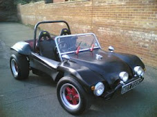


