Search This Blog

IRS Conversion - part two

24th March 2008
Previously in the last article I have cut away the body to allow access to install the IRS brackets which are part of the IRS conversion. I had downloaded the Internet article at http://bajaclub.co.uk/PDF_Documents/IRS.PDF from Airsouls. Although this article was written quite well it did not adequately explain the process of cutting in the brackets. As this is the most important part of the IRS conversion this was something that I would new to spend time over.

The first thing which was obvious about the installation was that I would have to either buy; make or borrow a jig that would give me the proper position of the IRS brackets. Fortunately after placing an advertisement on Vzi I was soon in the position of two IRS jigs. One thing I have found with using other peoples jigs is that as you haven't made the jig, its really important to ensure that you know how it works and more importantly if it does.

I decided that I would have to try the jig on a 1303s chassis to ensure that the jig was correctly aligned. It was noticeable straight away that 1303s brackets where different to the ones that are available today. The other obvious difference was that the frame horns seemed to be a different shape . The jig fitted into the IRS brackets on the 1303s chassis . The noticeable thing about the jig on both sides was that the tube that was attached to the end was short on both of the jigs. The reason for this was that the jig would not be able to fit into the bush on the furthest end of the bracket if it was any longer. I returned home happily in the knowledge that the jig was ok and a reasonable fit.

It was at this point that an child hood illusion was shattered. I had always thought that VW cars where superior because they used the metric measuring system way before we adopted it in the UK. When trying to locate a suitable bolt that would fit the brackets this turned out to be 1/2" UNC. Well as you can see the myth was not true.

I took the jigs back to the garage. The first thing I needed to do was to cut away the metal where the bracket fitted into the frame. You can see in the pictures I started by removing material from the flange that braces the frame horn to the torsion tube. I took the material away to the handbrake cable guides. I new I would have to remove more material and take the flange back further before the bracket would fit in and not foul the IRS Arm when it was in place. The next thing I was going to have to do was to use the jig to locate on the bolt hole on the side of the frame arm. To do this the jig would have to be placed on to the car.

I needed to remove more material from the flange on the frame horn so the length of the bracket would fit alongside the frame horn. With the Jig in place on each side the and done up enough for the arm of the jig to make contact with the frame arm. I could use a black marker to draw around the outside of the bolt hole. I then used a Starrett 1 3/4" or 32mm type hole saw to cut out the hole were the bracket protruded through. It is important to note that when you mark the holes you have marked the circumference of a circle.You must ensure you have a centre point of this circle before pop marking and drilling. This can be achieved by using dividers or compass. The hole can be troublesome to cut out as it is very tight to get a drill and Starrett hole saw into you may find that the only way to do this is to purchase right angle conversion for your drill, these are exceptional for getting into tight spaces. The one pictured right came with a key less 10mm chuck for £9.99. I added an £18, 13mm keyed chuck onto it so that I could fit the Starrett arbour which was 1/2" into it . With this hole cut out the bracket could be slipped into this hole and positioned on the rear torsion bar to gain its eventual position. I used this method to locate the position of the bracket on both sides. The main reason for this was that on the Baja club IRS conversion the hole was made too large. Additionally the bracket did not sit entirely in the hole so it had to be cut out precisely. The angle that the brackets protruded from the torsion bar where then compared and adjusted so they where the same, luckily no adjustment was needed. I cut the holes out easily and tried the brackets on each side. I found the driver side (left picture) still required more material to be cut from the flange to allow the bracket to be fitted and marked. This bought the flange under the handbrake cable and would mean that the cable position might need to be changed. It appeared different from the passenger side as it was not interfering with the bracket like the drivers side was.

With the holes cut and the bracket positions marked. The gauge of the metal could be seen easily with the holes cut and looked to be no more than 2mm. I could start removing material from the torsion bar end working towards the rear of the car. This was going to be a slow procedure of cutting a strip back then trying the jig and bracket in place until a good fit was made. I would start by removing half and then use smaller increments on each cut back. I new the end of the bracket was supposed to sit outside the frame arm thankfully to a picture in the Airsouls article on the bajaclub website.

Once the brackets where made to fit, the jig and bracket where then fully done up in preparation of the brackets being tacked in place. Before they where tacked in I went back and took more measurements of the original brackets to ensure everything was in line and in place. When I tried to get my Arc welder running on my Honda Generator I soon found that it drew too much current from the generator to weld with. I would have to hire a welder generator for machine hire company to allow me to get the brackets welded in and the new A Arms fitted.

Cont.
Rear Body Modification

12th March 2008
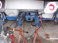
After the first attempt at installing the IRS brackets I realized that the rear body dropped quite low into the area where the new IRS A-Arms where going to fit. I had already cut down the drivers side battery box and removed the side of the frame horn ready to use the IRS bracket jig. I had been thinking about the frame horn trusses and new that they needed to fit between the upper shock absorber mounts in addition to needing to create space for the passenger side A-arm to move. The spare tyre well placed a bulge on the underside of the body that was directly in the way of any bar that would traverse the top shock absorber mounts. I was already committed to rebuilding the battery box bottom and decided that whilst I had access to the rear of the car that I would cut out portions of the spare tyre well laving enough space for the new IRS parts and the frame horn truss to fit. You can see from the two images above the differences in the bottom profile of the buggy. The height of the rear projections in to the chassis had been reduced substantially.

The picture to the right shows the inside view from the rear seat area. You can clearly see that the cut-outs follow the line of the battery box. With the areas rebuilt and the rear shelf extended to meet the new back of the spare tyre well area. This hopefully would leave enough clearance for the frame horn truss to be fitted, if and when I managed to find one for sale at a reasonable price.

Finally I was nearly ready to see if the new gearbox fitted.

Installing the IRS A-frame brackets - part one

11th March 2008
The fabrication of the Jig for locating the position of the IRS A-Frame brackets was not something I needed to do as I found a seller on www.volkszone.co.uk , who was wanting to sell the jig he had for building his own IRS. I picked up the jig from him and was soon aware that he had not used the conventional bolts that bolted the A-Frame in to position the brackets. The tubes that ran inside the brackets was only the size of a 1/2" UNC x 4" bolt. This did not give a steady position for the brackets and I decided that before using them I would have to check them against a real IRS chassis to ensure that they gave the correct position in practice. This would not be a problem as I new the location of a 1302s chassis that was bare at a friends workshop.

I decided that I would not be able to fully position the brackets, but decided to clean up the frame horns and remove the surplus material along where the bracket would sit. Once I had the jig problems resolved I would be able to cut into the frame horn to get the final position of the bracket.

I started with the off side of the car removing the brake hydraulic lines that where still left. It was pretty clear at this point that my battery box was to low to gain access to the bracket position. I was also worried that being so low the A-arm would hit the bottom of the box as the suspension moved. This was not going to be an easy process with the body attached to the car, but I decided it looked feasible. I started by drilling a hole in the fibre glass that I could push the blade of a jig saw through. This allowed be to cut along the back and the inside of the battery box several inches from its bottom. I then managed to use an angle grinder to cut from the inside of the box the outside edge of the battery box. The angle grinder was also able to cut the box around the torsion bar, which enabled the bottom of the box to be removed.

With the bottom of the battery box removed I had access to the flange that ran along the outside of the off-side frame horn. I started to cut the metal with the angle grinder and cutting disk alongside the handbrake cable. I was able to cut the material back all the way to the torsion tube. When I had finished cutting this area out I switched to a grinding blade and cleaned the of the paint. I knew I would have to build a new floor to the battery box at a later date but I was pleased with the progress I had made with the drivers side.

The weather forecast for the next few days was awful and I was not able to get into the garage to cut the other side down. I had decided I wanted to cut the fibreglass on the nearside of the car , which was rumoured to be for a spare wheel. This was ludicrous of course as there was no way a beach buggy wheel would fit in this space. The main reason for removing this area was to allow for the future placement of a German Kafer Cup type Torque Bar Kit. As seen on the left. The design of this needed to allow a bar to cut straight across the spare tyre well and under the rear seat rear of the buggy. Currently this was an expensive piece of kit and I wanted to see if I could build in space for it to fit should I be able to get hold of one or build one.

The weather was suspected to get worse so this was all put on hold for better weather conditions that where more favourable as the high winds had nearly took the garage door off already.

Removal of Spring Plates & Torsion bars

10th March 2008
The spring plates are attached to the chassis through a torsion tube and cover plate. The removal of the spring plates is an easy job that sometimes can be confused with a complicated one. The main construction of the spring plates and the way they interconnect can be seen in the diagram left.

The reason I was removing the plates was to make way for my IRS conversion. The IRS spring plates are much shorter and have a different size torsion bars.

You will need to gather together the following tools: a jack,(bottle Jack; or trolley jack), 14mm socket, extension,ratchet and spanner, A large hammer, a crow bar. Firstly if you are going to refit the spring plates it is useful to use a chisel to mark the spring plate position on the torsion bar. You will notice when doing this that the torsion bars are marked left or right respectively. As I was not intending to replace the spring plates and also had a spirit level with a LCD readout this would never be a problem.

The four cover plate bolts need to be removed first and these can be troublesome to get out especially if you have replaced your covers with the cheap chrome ones. The best method is to use a socket with the large extension. You need to drive this onto the bolt head with a hammer or mallet. Once you have the socket attached you can use the ratchet to remove the bolt. This method usually works for all four bolts but sometimes you can only get in with a spanner. With the four bolts removed the cover plat can be removed and pulled off. This usually leaves a rubber or urethane bush on the spring plate. Remove this and put in a safe place. Position your jack underneath the end of the spring plate and jack up the plate so that it is no longer resting on the shoulder of the torsion tube bracket. Double check this is firm. The reason for placing a jack here is to ensure that if the spring plate kicks back under tension the jack will hold it and stop it forcibly slicing through any body parts. Obviously keep your feet and hands from under the spring plate for safety reasons. With the jack placed you can take your sledge hammer and start hitting the inside of the spring plate to ease the spring plate out of the torsion tube and off the ledge it is sitting on. You may need to get the crow bar on here to get leverage. If the spring plate is extremely stubborn
it sometimes helps to tap the spring plate all around the outer casing enclosing the torsion bar. With all three of these procedures the spring plate should move out. Once the spring plate has moved out of the shoulder. You can let down the jack and take the pressure slowly of the spring plate. You should be then able to withdraw the spring plate and torsion bar by tapping the spring plate until it is able to be withdrawn.

This was then repeated for the other side. Surprisingly there was enough room in my small garage to get the torsion bars all the way out.

Removal of the AB Gearbox in preparation for the AT box .

9th march 2008
The proposed IRS conversion was going well I had the A-Frame Arms ready to be fitted to the chassis. I had bought a 1302s IRS gearbox with AT code that had a higher ratio drive as it was originally made for a 1600 engine. This would better suit my engine. I had bought brackets to fit the IRS arms on a visit to the new SSP/VW heritage site.The brackets would need to be cut into the chassis and welded onto the torsion tube. To make way for the brackets to be welded into the chassis the gearbox would have to come out.

The removal of the gearbox is something best done with two people. I must thank my friend John for his help this morning. The removal process is quite straight forward, it is not necessary to remove the brakes from the drive shafts, however the brake hydraulic lines must be removed from the slave cylinders and the handbrake cables must be undone at the handbrake. I have already removed the drums as I wanted to lose the weight from the gearbox, additionally I was intending in replacing the drum brakes with a rear disk conversion. I had also removed the flexible hydraulic lines at this time.

Before undoing the gearbox bolts you need to remove the three bolts that hold the lower part of the drive shaft to the drive shaft. These are torqued up so you will need to use quite a lot of force to get them undone. You can use a length of tube on the end of a socket wrench, but in practice they can be undone with two 19mm spanners. With the three bolts undone you can unclip the rear bump stop. This will allow the drive shaft to separate from the swing axle. With the three bolts undone you must ensure that you have no cables or wiring attached to the gearbox. This usually comprises of the reversing light switch at the front of the box, the starter motor wiring and the clutch cable. You will need to release the gear linkage where it is connected to the gearbox. This is located under a small cover plate behind the rear seat and is secured down with a small Philips screw. With the cover plate off the linkage will be exposed. The linkage is secured by a 9mm square bolt that goes through the linkage, it may have a locking wire securing it which will needed to be cut off. With the bolt removed the linkage can be separated from the gearbox. With all these items removed you are ready to get at the gearbox bolts.

The front gearbox bolts are situated on and below the torsion bar tube in the centre. The two bolts can be undone with a 19mm spanner. The rear gearbox bolts are 27mm and you will need to get the proper spanner or socket to get them out. They are also torqued up to 166ft/lbs and will need a large amount of effort to get them undone. With all the bolts removed the gearbox can be pulled backwards and out of the car. You must first pull the drive shafts from the swing arms and then with a friend get a good grip on the box and pull it backwards. The gearbox will come backwards out of the rear arms. Be careful as it comes out as its weight will increase as its manoeuvred out and the gearbox is free. You will also find it quite awkward as it shifts out . Ensure you both have a good grip and be careful not to drop it.

With the gearbox out it is noticeable that the front mount on the new and old gearbox is different. The AT gearbox has a 1302s mount which has three bolts on the gearbox. The AB box has only two. I would have to swap the front nose cones from the two boxes.

With the gearbox removed it is noticeable how far the battery box comes down . I would have to cut this back and re fibreglass a new base in the box higher up.

It was also noticeable that the area that the IRS brackets would be quite difficult to cut into the chassis with the body on.

I was beginning to wonder if this was the best opportunity to have the chassis Zinc hot flame coated. With the chassis out the welding would be easier to do as I could weld up the IRS brackets on my drive way before taking the Chassis to have it blasted and zinc coated. This would also allow me time in the garage with the body of the car to re-fibreglass the underneath.

Preparing for the IRS/Gearbox conversion

6th March 2008
The garage was starting to fill up before I started on the stripping down of the back end. As the gearbox was coming out to be replaced by an IRS 1302s version, I stripped down the brakes to make this removal easier.

The removal of the wheels and drum brakes where fairly straight forward. The wheel bolts where loosened whilst the car was on the ground. As when the car was to be put on axle stands this would be easier to get the wheels off. Once the wheels where off, the drums where visible to be removed. These are secured with a cotter pin and large nut. The nut is torqued up to around 250ft/lbs so you will need a long bar with the handbrake latched on before it will budge. With this nut off it is best to back the pads off. These are retracted by rotating little star adjusters which re hidden in the back of the backing plate by two rubber bungs. You can rotate the star adjusters with the correct tool or a medium sized flat blade screw driver. Turn one at a time to ensure you are not winding them the wrong way and locking the brake up further. With the brake pads backed off the drums can be withdrawn from the shaft. Personally I use a long socket-set extensions held horizontally against the drum and between the backing plate. This can then be hit with a hammer to remove the drum. It is sometimes necessary to move the bar to the other side of the drum so that the drum comes off evenly. The backing plates must have the handbrake cable unhooked. This can be achieved by undoing the nut at the back of the plate that bolts the cable tort. Releasing this gives enough slack for it to be unhooked. The brake cylinder also needs to be disconnected and sealed up.The backing plates are held on by four 14mm bolts with these removed the drive shaft bearing cover plate can be removed and then the backing plate will come off. I placed the drive shaft bearing covers back on so that the bearings would be sealed.

Removing the the shock absorbers was just a case of undoing the respective bolts and removing the shock absorber. It is interesting that the only difference between the IRS and Swing Axle shock absorbers is the wider bush that sits at the bottom of the shock. The bottom bush can be removed by driving in a new one. I had removed the longer bushes from an old set of IRS shocks that I bought with the IRS parts.

You can clearly see in the picture right above that there would need to be some work with the fibre glass body sections to allow the IRS A-Frame arms to travel in their plane without hitting the body work.

I needed to get a friend to help me remove the gearbox as this was a heavy item that would need to be balanced on the jack whilst it was being undone. I would attempt this when a friend was available.

Rebuiding IRS arm bearings and axle shafts

3rd March 2008.
With the urgency of pulling the engine out now gone and the engine now sitting waiting to be rebuilt. I decided that I needed to get on with the IRS conversion that I had already started before I found the problem with the debris in the crankcase.

I decided that I was going to renew most of all of the components on the A Arms. This meant I needed to purchase new bearings oil seals and other miscellaneous sundries.

I started with trying to locate the bearings, several telephone calls later I was wondering what's was happening to the parts industries. The only bearings that it seems that I could buy where the new type of needle bearings. This was annoying as I already new that roller bearings where much better and ran much smoother giving less drag and longer life.

The problem being that the needle bearings where made from small cylinders that run in a steel cage made from pressed steel. The ball bearings on the other hand had small spherical bearings in a cage made from several parts. The friction surfaces where much smaller and the tolerances in the bearing where much higher.


Needle Bearings (above left) ............................... ,Ball Bearings (above right).

In the pictures above you can clearly see the differences in the two bearing designs and why the ball bearing or ball race provides less friction and better wear.

After discussing this problem with come friends I found out that you could purchase bearings from a bearing company and that they would usually measure your existing bearings and come up with a match. I found a company called Kent Bearings in Hastings East Sussex. They provided me with the correct size bearings. Interestingly enough the two bearings sizes where the same. This was interesting as most car suppliers supplied the rear set of bearings at a higher cost?

I bought the bearings and bought some Castrol LM bearing grease. I found that the oil seals came in a kit for the cars with swing angle and not for IRS. On closer examination the parts in this kit where exactly the same as the parts that could be sourced separately for the IRS.

The Axles are assembled from the back bearing. This is inserted first, then then the circlip and then the oil seal. All of these items need to be greased with the LM lube before they where assembled. Once these components where set in place the inner spacer (The spacer with the concave side was placed into the oil seal with the concave side facing the outside. The axle was thoroughly greased and then knocked into the A-Frame with a wooden mallet. 6oz of LM grease is then packed into the front of the A-Arm cavity. The inner spacer can then be lubricated and slid onto the axle. Once all this has been done you are ready to insert the outer bearing. This is slightly harder to achieve as you need piece of tubing the size of the outside bearing casing and about 250cm long. You can slide this over the axle and then knock the lubricated outer bearing into its place. The oil seal can then be seated over the bearing and the external spacer can be set on the axle and slid into the oil seal.

This process leaves you with the axles correctly installed in the A-Arm. You can add the cover plates at this point but I wanted to get hold of some calliper brackets before I placed them firmly in place.

Parts.
Grease: Castrol LM Lithium grease
Ball Bearings:
FAG 6206.c3 15010719

Engine removal

1st March 2008
It was a sunny day and I had started the afternoon by removing the distributor drive shaft and the alternator and pedestal to see if there was any way I could see into the engine and spot the pump debris. This was soon written off as a bad idea as the access was restricted.

I started removing the wiring to the coil , the distributor and the alternator. I removed the fuel line and started on the three nuts and one bolt that held on the engine. These came undone fairly easily and with the help of a good friend and a jack was able to get the engine out and onto the floor. We moved the engine to the side of the garage and I took look at the transmission.

The first observation's showed that where I had rebuilt the battery compartment and the tyre well the new IRS components would hit the underside of the body, this was annoying as it was obvious that the body work was probably fitted to an IRS chassis before my changes. I would have to cut the body work back to allow room for the new A-Arms to rise up to the bump stops. I also noticed that my alternator B+ line had scorch mark in it and it looked like it had been sitting on the exhaust.

I would have to put axle stands under the rear frame horns and jack up the rear of the car to raise the rear wheels of the ground. This would allow me access to the gearbox and allow me to remove the rear wheels and gearbox assembly.