30th June 2009
The idea of rebuilding the bearings of a beetle engine to most people is something best left to the technical amongst us. To be honest this may be true as you get a more accurately built engine , however it is not something that cannot be done in your own garden shed.
Principally the hardest part of rebuilding an engine is changing the main bearings. There are many problems with this as cases are sometimes line bored to accept slightly larger bearings. With this in mind you must be sure which bearing set you need to order. Most good suppliers are only to helpful with this and armed with the correct bearings and your bearing saddles not having any strange grooves or lumps out of them then you can fit the bearings as detailed below. If the bearing saddles are pitted , scored or otherwise trashed you will need a line bore through the bearing saddles so that the bearings can be seated properly. Generally speaking if you are having a line bore its best to order the bearings through the company doing the line bore to ensure you have the correct ones.
The next problem most people encounter is to remove the bearing that sits between the camshaft drive and the number 2 rod shoulder. This is something I have always had done in the shop but to be honest its not as difficult to remove as you would think. To remove the bearing you will need either a three pronged puller or a proper crankshaft bearing puller which unfortunately are fairly expensive. The other thing you will need is plenty of heat , now we are not talking about a paint stripping gun. We are talking about a butane torch that will heat the bearings up to a temperature that they will expand enough to slip of the crank shaft. When you have both of these you can remove the oil slinger by removing the wood ruff key with a screwdriver and hammer to tap it out this will give access to remove the circlip use a screw driver to prise the circlip of the end of the crank. The bearings can then be heated and heated some more until they are hot enough to enable the puller to pull the camshaft gear and distributor gear off. Be careful when they are off as they will still be very hot.
With the camshaft drive off you can slide the old bearing of the crankshaft. You need to check the bearing surface for any defects. Now putting them back is not the same procedure as taking them off. Ensure that you put the new bearing on with some bearing compound such as Joe Gibbs Assembly lube grease, which will help bed the bearing in. The next important thing much overlooked is to ensure the camshaft bearing goes back on with the two dots facing towards the end of the crank. The curved in side of the drive needs to go next to the bearing. Now to get the drive back onto the crank you will need to heat up the camshaft drive again. The easiest way of doing this is to pop down to Tesco and buy a cheap saucepan and fill it with engine oil and put both on a camping stove. Watch for bubbles appearing from the drive. When you get this the drive is hot enough to be dropped back onto the crankshaft. Be warned get it the right way round! Also don't go hotter or you will set the oil on fire. Fit the racer spacer next and then use the same process to heat up and fit the distributor drive. Finally the circlip can be replaced. The oil slinger must then be placed back onto the crankshaft it may be necessary to remove the pulley wheels wood ruff key to enable to fit the slinger the concave side must face outwards.The other bearings can then be lubed up and placed on to the crankshaft bearings with the exception of the middle one which must be fitted to the case.
Personally I did not fit my crankshaft at this point but instead checked the play in the con rods which in my case was considerable. The tolerance for measure this is done by inserting a feeler gauge down the side of the con rod. There should be no more than 0.016-inch min by axial measurement. The bearings can be bought for very cheaply and can make a considerable difference if the crankshaft saddles are in good condition. Ensure that you remove and re fit the con rods the same way up. All the notches should face up and the con rod marks should appear the same side for the top as for the bottom. The con rod bolts need to be torqued up to 23lbs. The new bearings made an impressive difference remember to lube them in using the same pre-assembly lube as the crankshaft. With the rod bearings fitted the crankshaft can be fitted on to the bearing saddles. remember to check the dowels are in situe and are in good condition. The bearing need to be aligned so that they fit onto the dowels and the crankshaft will drop into place.
I decided that I wanted to fit a higher lift camshaft to the engine and had previously chosen an Engle W110 for this engine. I used a Billet Alloy camshaft gear that I had from a previous test comparison. This had been balanced on a lathe as its original casting was poor. The camshaft and drive can be fitted after the cam followers have been lubed and inserted into the case. Ensure that the top of the cam followers have also been lubed. the camshaft bearings are press fitted into the casing on both halves. The larger shouldered bearing fits nearest the drive and the bearing decrease in size towards the flywheel. The camshaft needs to be meshed against the Camshaft . The two dots on the drive gear should nestle neatly either side of the dot that is on the cam gear. This is the correct synchronisation of the two gears and is vital for the timing of the engine.
The two half's of the crankcase can be mated to test for binding on the crank. If the crankshaft is free and able to be moved the two half's can be separated and the camshaft seal can be glued with sealant into the case. I used blue hymelar as a case sealant as it stays tacky whilst your assembling. The six central nuts can be tighten remember to diagonally tighten down. Check the crankshaft can still move by placing the front pulley wheel in situe and then place the peripheral nuts and bolts around the case.
The oil pump can then be fitted into the case a soft rubbermallet can be used to push the oil pump into place. YOu must remove the gears before doing this as they need to be keyed into the camshaft. With the oil pump in place the small block is almost complete rebuild was almost complete. I needed to purchase a full flow oil pump cover as I had decided to go full flow.
AS41 Magnesium Alloy Case Welding the tricks
23rd June 2009
The Magnesium/Aluminium case design of the AS41 case i renown for being one of the lightest design engine cases even by today's standards. This was the brilliant invention of the VW factories in Germany who originally built the engine to power planes. The downside of this design is that the Magnesium/Aluminium alloy was a mixture that was hard to weld. The obvious risk of this being igniting the Magnesium whilst welding so that the hole part you were welding burned with a large flash eating away its form. Traditionally welding these materials takes a great deal of experience as the welder needs to be aware of the composition and must apply only enough heat to weld and not combust. It is also paramount that you have a hammer with you available to beat the crap out of the area you are welding so as to knock the burning magnesium out of the area. The downside of this is that i can leave a larger hole than you start with. Crucial to the weld is also the composition of rod that you use and traditionally the flame is better controlled by a tig welder. Most people believe wrongly you need an Aluminium rod with a Magnesium content to weld the AS41 case. The result of this I found out quite quickly was not the answer and the shop that I asked to weld the case up produced the hole filled and taped but not surprisingly the plug they had welded in did not bond to the case and was simply able to be pulled out.
The correct welding rods to weld an AS41 case are in fact Magnesium rods with a low percentage of Aluminium. The actual percentage being 8% Aluminium to 92% Magnesium. These are available from Armour supplies Ltd in Hastings, East Sussex UK .
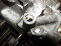
Withe the case welded so that the main gantry was plugged I was able to get the case re taped with the 3/8" NPT tap. I used a workshop for this and had to remove all the engine main studs so that it could be mounted in their mill. you can see from the photograph that I decided to have the area made bigger so that the thread had a good fetch into the casing.
The finished plug looks stronger and more durable than the original. I am very suprised this can be done and it blows a large rasberry in the faces of everyone that says it cannot be done or to put it a better way the people that have kept this a secret from us for a long time are now all aware we all know,. I look forward to seeing a lot more cases re welded in the future.
As the answer is a vertible YES!!!!!!!!!!!!!!!!!!!!
Fan housing design and overturning traditional ideas
14th June 2009
With the disaster of my engine case I had to find a company that could weld and re tap the oil gantry. This was a difficult task and in the meantime I turned my attention to the other parts of the engine that needed cleaning up. I had two companies that I had approached to do the case work but both were taking time to come back to me.
Originally I had thought that I would just cut weld and chop of the air outlets from the fan housing but a friend had put a thread on Volkszone about this and surprisingly there had been some technical testing done by Jake Raby's research into engine temperatures and fan housing design. That indicated that the Fan housing design was constructed to have integral vanes that directed the air flow inside the housing separating air flow from the engine and diverting it to the housing outlets. It appeared from the discussions that the general consensus including my own that simply blocking of the vents would cause air flow turbulence in the coursing that would effect the fan housings overall ability to cool the engine.
I have included a picture of the internals of the VW fan housing courtesy of www.offroad.net which is also a source for the information here in comparison. The scat housing picture courtesy www.newlancsvwclub.co.uk is definitely missing some of the internal vanes and although seems to produce adequate cooling there must be reasons why VW included the extra vanes in the first place. The solution suggested by newlancsvwclub seemed to be to cut the whole outer edge of the fan housing down to remove the air channel that would cause the air buffer. This in practise was a very easy option and the rough shape can be seen on the following picture. The internal structure of the fan housing that directs the air to the vents can be un tacked from the fan housing and pulled out to make a new curve that follows the new line of the housing as detailed by the green line.
I started on my fan housing removing first the air outlets with an angle grinder and thin cutting disk. The outlets came of fairly easily and from the holes that were left I was able to see the internal vane that was going to become the outside of the new housing. It is important to leave about 2" of metal at the top of the housing to keep the two halves held together in the correct alignment. With a flexible ruler I marked a line on the outside of the housing. With one side cut away the front side could be trimmed to ensure it was closer to to the vane. The rear section was then cut away and the vane pulled out to meet the new curve. It can be seen from the picture that the vanes do not meet the top of the fan housing. I cut pieces from the cutoffs to make material to fill these gaps. Obviously you could bend the internal vanes to make any new shape you desired, however I was attempting to get the best cooling possible from the design and though that the curved top lended itself to this application.
With the design and metal work cut and established the fan housing needed to be welded up . This is not as easy as it looks as the thin tin ware is quite thin. I used a MiG welder to tack up the housing at opposing points around its perimeter . This gave the construction a better stiffness that allowed the perimeter to be tacked up. The result of he welding process is not as neat as the original design and it as obvious that I would need to prep the housing before painting. After Angle grinding the surplus weld of the housing I decided to try p38 filler to smooth the outline. Discussions with a friend regarding this pointed out that the files likely to chip off from the housing during its use and that I would be better to have the outside prepared by fibre glass. I took the fan housing to a Friend Ash who created a mold from the housing and re profiled it to make a better curve. This was then bonded on and the whole housing was painted and primered. I painted the rest of the tin wear in primer and needed to get a nice cool day to buy some 2pac in spray cans so that all the tin wear could be blacked up . The tin ware was looking excellent and I needed now to get the case repaired. This was looking very interesting as most posts found on Volkszone said it was a potrntial arsonists or pyrotechnics dream come true as the Magnesium base AS41 case just would turn into a large roman candle. Was it going to be possible or was I just going to have to purchase another case or complete engine?
Some pictures courtesy of www.newlancsvwclub.co.u and www.offroad.net.
Labels:
Cooling,
Fan housing,
Fan shrowd,
Scat housing
A new 1300 dual port engine
5th June 2009
I had started to realise that with the break up of my relationship that my new 2L engine was going to be something further distant that I had planned. I was planning to have the engine in by the end of this year and with the custody fight and various other depressing events I needed to find a solution that would get the engine situation resolved as my friend had been very good to lend me his engine lump but obvuously I wanted this resolved. I managed to purchase a 1300 dual port lump that had been dry stored in a lockup for some years. Although the engine had some end float outside the allowed parameters generally it looked in good condition.
Initially I decided that the engine would need stripping and the piston rings would need replacing , but I also found that the con rod bearings and crank bearings really could do with renewing. I really had not planned for this and had decided against renewing at this time until i was placing the pistons back on to the case and pung one of the pison ring clps accidentally into the casing.
This normally would have been a disaster but to be honest I was already considering stripping the block down and decided that this was now had to happen. You can see from the diagram that the gudeon pin clip was lodged beneath the camshaft and was totally uneccessable from the oil plate. I took out the crank hsaft and camshaft and cleaned the engine parts thourougly with gink and then jet washed them off to remove any final engine residue.
The engine casing parts cleaned up fairly well and without the use of a dishwasher I was unable to get them as clean as I had with the other cases I had worked on. I couls ssee from the bearing journals that the crank had not damaged the casing and the case was in good condition. I decided whilst I had the case apart that I would full flow the oil system so that it would be able to cope with any future upgrades. This consisted off tapping the casing outlet of the oil pump for a 1/8" NPT thread and tapping the main oil gantry to provide a return a 3/8"NPT thread. The oil pump casing was quite easy to tap and this can only be done with the negin in half. The 3/8"NPT main return thread was a hole differant ball game. The thread would not take in the casing and instead just powdered up and dug a hole . This was a disaster as there was not much room in the casing to put in a case saver. I new that I would have to delve into the world of case welding something believed to be a Pyrotechnics black art.
Labels:
1300,
Engine Case,
Rebuild,
Welding
Subscribe to:
Posts (Atom)