9th March 2007
The day had started badly with my engine valve re-tune not fully riding me of the problems of backfiring and popping that I had been plagued with since fitting the twin Weber 40IDF carburetors.
I was sure that there had to be a reason for the engine noises as the engine seemed to run much better when it was stationary. There had to be a loose component or something that was failing during acceleration. I considered the electrical system and was sure that the ignition system was solid as had already checked this out when I fitted the new spark plugs.
If the ignition system was OK this only left the fuel system. One possibility was that the fuel fuel reservoirs in the carburetter float chambers was not full enough and was moving whilst the car was accelerating. The problem with this was that I had already had the float levels set up by a specialist and new they where correct.
After eliminating everything else I was left with the fuel regulator which regulated the fuel supply to 4 psi. I removed the regulator from the fuel system fuel lines and tried again , giving the car a short run. To my amazement the problem had disappeared. It seems that my corroboration problems had been plagued by a bad regulator that I had bought from eBay. I was not sure if it was my mounting or adjustment as the regulator had no gauge. Either way my buggy sounding more like it should.


Tuning up - Adjusting my valves
8th March 1007
My engine had been coughing spluttering and backfiring for several months and my attempts to solve this by corroboration had not come to much fruitfulness.
I decided that as my cylinders #3/#4 were making a larger than normal tapping sound and it was also noticeable that the exhaust from these cylinders was considerably colder than cylinders #1/#2 that I should tune up my valves
The procedure for a valve tune-up is fairly simple as long as you have the area clean , the correct tools a feeler gauge; 13mm spanner; 19mm spanner and a large screwdriver and a smaller screwdriver.
Before starting I remembered to purchase some new cork gaskets for the valve covers and put my ground sheet down under the cylinders #1 and #2 . The first cylinder is easy to find as you can remove the top from the distributor and crank the generator nut with a 19mm spanner until the rotor arm points to the line on the perimeter of the distributor body. With this set the feeler gauge can be used to check or set the valve clearances for cylinder #1. I used the .008" and .006" blades from the feeler gauge to check that the adjustment between the rocker arm and the top of the valve stem was .006". By trapping the 0.06" blade between the adjuster and the stem and doing the adjuster up until you can just slide the .006" blade in and out with friction. It is possible to then do up the lock nut and check you have the correct setting by trying to insert the .008" blade. If this is successful and the .008" blade fits you have the wrong setting and must go back and try again with the 0.006" blade. This has to be repeated for the inlet valve and the exhaust valve.
The whole engine has to be moved backwards by 180 degrees so that cylinder #2 is in firing position. This can be accomplished by using the 19mm spanner to rotate the generator anti clockwise so that the large pulley on the crankshaft travels 180". Once done the valves for cylinder #2 can be set in the same manor as cylinder #1.
At this stage two cylinders have been adjusted and #3/#4 remain. You can keep rotating the engine by 180 degrees a further two times adjusting the valves on #3 and then #4.
Once completed you can replace the valve covers with the new gaskets that you have purchased earlier.
I started up my engine and was happy to see an improvement , however before long there was a slight metallic sound coming from #3/#4. I shut the engine off immediately.
I presumed something had come loose...
I had to wait another 24 hrs to let the engine cool down and could not get back to remove the valve cover until the following morning. Once I had the valve cover removed it was clear what had happened. I had encountered some problems getting the valve cover on #3/#4 and had inadvertently knocked the retaining pin off the rocker assembly. I found the pin and three washers complete in the bottom of the cylinder head. Replacing them was fairly simple and the pin was a tight fit. I carefully replaced the valve cover after cleaning up the gasket and restarted the engine.
The engine fired up beautifully it sounded like it was running much better and producing more horsepower. I reved the engine and found a nice rich sound of power. I jumped in and backed the car out of the garage and put the buggy into first gear and pulled away. The engine started to pop and splutter and sounded like it was running unevenly.
This was very odd. I could run the engine stationary perfectly but could not drive the car without it spluttering and making awful noises.
I would have to have a rethink ...
My engine had been coughing spluttering and backfiring for several months and my attempts to solve this by corroboration had not come to much fruitfulness.
I decided that as my cylinders #3/#4 were making a larger than normal tapping sound and it was also noticeable that the exhaust from these cylinders was considerably colder than cylinders #1/#2 that I should tune up my valves
The procedure for a valve tune-up is fairly simple as long as you have the area clean , the correct tools a feeler gauge; 13mm spanner; 19mm spanner and a large screwdriver and a smaller screwdriver.
Before starting I remembered to purchase some new cork gaskets for the valve covers and put my ground sheet down under the cylinders #1 and #2 . The first cylinder is easy to find as you can remove the top from the distributor and crank the generator nut with a 19mm spanner until the rotor arm points to the line on the perimeter of the distributor body. With this set the feeler gauge can be used to check or set the valve clearances for cylinder #1. I used the .008" and .006" blades from the feeler gauge to check that the adjustment between the rocker arm and the top of the valve stem was .006". By trapping the 0.06" blade between the adjuster and the stem and doing the adjuster up until you can just slide the .006" blade in and out with friction. It is possible to then do up the lock nut and check you have the correct setting by trying to insert the .008" blade. If this is successful and the .008" blade fits you have the wrong setting and must go back and try again with the 0.006" blade. This has to be repeated for the inlet valve and the exhaust valve.
The whole engine has to be moved backwards by 180 degrees so that cylinder #2 is in firing position. This can be accomplished by using the 19mm spanner to rotate the generator anti clockwise so that the large pulley on the crankshaft travels 180". Once done the valves for cylinder #2 can be set in the same manor as cylinder #1.
At this stage two cylinders have been adjusted and #3/#4 remain. You can keep rotating the engine by 180 degrees a further two times adjusting the valves on #3 and then #4.
Once completed you can replace the valve covers with the new gaskets that you have purchased earlier.
I started up my engine and was happy to see an improvement , however before long there was a slight metallic sound coming from #3/#4. I shut the engine off immediately.
I presumed something had come loose...
I had to wait another 24 hrs to let the engine cool down and could not get back to remove the valve cover until the following morning. Once I had the valve cover removed it was clear what had happened. I had encountered some problems getting the valve cover on #3/#4 and had inadvertently knocked the retaining pin off the rocker assembly. I found the pin and three washers complete in the bottom of the cylinder head. Replacing them was fairly simple and the pin was a tight fit. I carefully replaced the valve cover after cleaning up the gasket and restarted the engine.
The engine fired up beautifully it sounded like it was running much better and producing more horsepower. I reved the engine and found a nice rich sound of power. I jumped in and backed the car out of the garage and put the buggy into first gear and pulled away. The engine started to pop and splutter and sounded like it was running unevenly.
This was very odd. I could run the engine stationary perfectly but could not drive the car without it spluttering and making awful noises.
I would have to have a rethink ...
Building A Compressor, My Clark Pioneer 100+ SIP HobbyAir 210
3rd March 2007 My Clark Pioneer 100 compressor that I was kindly given by a friend as it did not work was only capable of 3.5cpf displacement as it ran at .6hp, this means that it would only run small air tools and the LVLP newer guns at 8Bar .
I had a SIP HobbyAir 210 1.5Hp compressor without a tank that was capable of 7.5 cfm output that I felt would give the compressor more power and would hopefully power the HVLP guns on the market as well.
I decided that I could mate the two compressors and started by removing the plastic cover of the SIP HobbyAir. This was easier said than done as the bolts holding on the cover where recessed into the plastic so far that I needed a box spanner to reach in far enough to get them undone. Eventually I found a suitable box spanner in one of my toolboxes and got the plastic lid off. The HobbyAir was similar in construction to the Clark model but a lot smaller and lighter. I presume this was due to the HobbyAir being newer. I removed the Clark compressor motor by undoing the housing bolts and then the air and power lines that can be accessed under the switch panel.
It looked as if the Hobby Air would fit in the cradle of the Pioneer base. It would not l ine up with the bolt holes but I soon created some new bolting positions and started to work on the wiring.
I figured it was best to marry up the wiring in such away that if the Hobby Air compressor would not work with the Clark tank that I could easily put the Clark compressor motor back on and rebuild the HobbyAir to get me back to what I started with.
The wiring was pretty easy and I managed to bend the air pipe so that it reached the output from the Hobby Air.
The pump power up.
The capacitor on this model was CBB60 a 25 uf EN600252-1 starter cap

I was hopefully now in the possession of a 7.5cm 8bar compressor. I could not run a long test as my 4 month old daughter was in bed. I would find out if my creation lived another day.
I would have to make a new cover for the compressor engine and fan another day.
 My Clark Pioneer 100 compressor that I was kindly given by a friend as it did not work was only capable of 3.5cpf displacement as it ran at .6hp, this means that it would only run small air tools and the LVLP newer guns at 8Bar .
I had a SIP HobbyAir 210 1.5Hp compressor without a tank that was capable of 7.5 cfm output that I felt would give the compressor more power and would hopefully power the HVLP guns on the market as well.
I decided that I could mate the two compressors and started by removing the plastic cover of the SIP HobbyAir. This was easier said than done as the bolts holding on the cover where recessed into the plastic so far that I needed a box spanner to reach in far enough to get them undone. Eventually I found a suitable box spanner in one of my toolboxes and got the plastic lid off. The HobbyAir was similar in construction to the Clark model but a lot smaller and lighter. I presume this was due to the HobbyAir being newer. I removed the Clark compressor motor by undoing the housing bolts and then the air and power lines that can be accessed under the switch panel.
It looked as if the Hobby Air would fit in the cradle of the Pioneer base. It would not l
 ine up with the bolt holes but I soon created some new bolting positions and started to work on the wiring.
I figured it was best to marry up the wiring in such away that if the Hobby Air compressor would not work with the Clark tank that I could easily put the Clark compressor motor back on and rebuild the HobbyAir to get me back to what I started with.
The wiring was pretty easy and I managed to bend the air pipe so that it reached the output from the Hobby Air.
The pump power up.
The capacitor on this model was CBB60 a 25 uf EN600252-1 starter cap

I was hopefully now in the possession of a 7.5cm 8bar compressor. I could not run a long test as my 4 month old daughter was in bed. I would find out if my creation lived another day.
I would have to make a new cover for the compressor engine and fan another day.
R/H Sidepod Respray & Balancing the Carbs.
2nd March 2007
 After fixing in the battery compartment I was starting to run out of critical potential fails that would stop me getting a MOT. I new that the engine was running badly and that the drivers side pod need to be blacked out as it was white. This was a fairly straightforward procedure which unfortunately needed a couple of warm days in succession to do as the temperature needed to rise for spraying.
I used black satin spray from a spray can on top of car primer. This provided a good coverage that I new would come of in the summer if my planned respray went ahead. The sunshine was lovely and I was waiting around for the side pod to dry sometime wishing all the time to go for a drive.
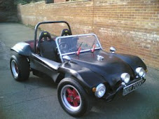
The side pod eventually dried and I had had the opportunity to fiddle with the carburetor balancing whilst I waited. I had managed to warm the car up to a good temperature and the work I had done previously on the linkage rods made it easy to get a good idle. The Buggy was starting to sound great. This made things worse as now I really wanted to go for a drive. I bolted on the side pod and ran the car around the garage complex . It was now pulling like it should and to be honest in all probability should pass an MOT. I new that this would be a while before I could get the buggy MOT'd as it needed to be weighed and I had to line this up with someone.
The pictures were taken on a mobile phone the day after the work was done they had to be taken inside the garage as it was raining and this is why the pictures are low quality.
I also had to arrange insurance and the three things needed a cash injection of around £200-00 before i could get the car on the road.
 After fixing in the battery compartment I was starting to run out of critical potential fails that would stop me getting a MOT. I new that the engine was running badly and that the drivers side pod need to be blacked out as it was white. This was a fairly straightforward procedure which unfortunately needed a couple of warm days in succession to do as the temperature needed to rise for spraying.
I used black satin spray from a spray can on top of car primer. This provided a good coverage that I new would come of in the summer if my planned respray went ahead. The sunshine was lovely and I was waiting around for the side pod to dry sometime wishing all the time to go for a drive.
The side pod eventually dried and I had had the opportunity
 to fiddle with the carburetor balancing whilst I waited. I had managed to warm the car up to a good temperature and the work I had done previously on the linkage rods made it easy to get a good idle. The Buggy was starting to sound great. This made things worse as now I really wanted to go for a drive. I bolted on the side pod and ran the car around the garage complex . It was now pulling like it should and to be honest in all probability should pass an MOT. I new that this would be a while before I could get the buggy MOT'd as it needed to be weighed and I had to line this up with someone.
The pictures were taken on a mobile phone the day after the work was done they had to be taken inside the garage as it was raining and this is why the pictures are low quality.
I also had to arrange insurance and the three things needed a cash injection of around £200-00 before i could get the car on the road.
Building the battery fastening device.
25th Feb 2007..jpg)
OK before we start no Darth Vader or Daft Ader comments or wow that's an improvement. Caught in the act !
The day before I had spent the day looking around the buggy looking for jobs that needed to be completed before the M.O.T. This culminated with the front number plate being fastened to the bumper with self tapping screws and the formulation of the idea of a way to hold the battery in place as I had been recently told that the MOT regulation requires that the battery be able to stay in position with the vehicle upside down. I decided to sketch out some ideas that could be constructed from some angle iron. The premis was simple as i needed to have a bar across the battery and then some screws down each end that would hook into a base. The base could be constructed from a frame welded from 1" angle iron, the top from 1/2 angle iron and the securing bolts from 6mm steel rod.
I cut the 1" angle iron with an angle grinder so that I had one of the angles removed and a flat piece of steel about 6" long. The end I made up from 5" of angle iron and drilled a hole in the centre to take the bolt. I new this would needing welding and only had my trusty Sealey Mig 100XT to weld it as my Arc welder was at my fathers. I had not used the Mig for a while so as with all Mig welders it needed a clean up before I attempted to weld with it. The welding material was rusty and this had to be removed until clean material was available and the tensioner had to be adjusted. You should never attempt to weld with a.jpg) MIG welder that has rusty wire as it can block up the welder and causes the mechanism to slip as the rust acts as a lubricant.
MIG welder that has rusty wire as it can block up the welder and causes the mechanism to slip as the rust acts as a lubricant.
I welded the framework up easily welding both sides of the frame to provide.jpg) a good weld. This made a nice solid base and I finished the welding on the first end and was soon onto the other end. I am glad I cleaned up the MIG as it was performing beautifully and creating good solid welds on the Angle Iron. You can see in the picture opposite that the base of the battery compartment was taking shape. I cleaned the welds up with my Angle Grinder and packed the welding equipment away and returned to the garage.
a good weld. This made a nice solid base and I finished the welding on the first end and was soon onto the other end. I am glad I cleaned up the MIG as it was performing beautifully and creating good solid welds on the Angle Iron. You can see in the picture opposite that the base of the battery compartment was taking shape. I cleaned the welds up with my Angle Grinder and packed the welding equipment away and returned to the garage.
Now you may ask why I welded at my house when most of you are aware that I have a 2.7KW Honda Generator, the trouble is the MIG seems to use about 2.8kw at peak and the welder trips out. I will have to service the generator at some point and try this again as most information on the net says this combination should.jpg) work.
work.
In the garage I heated up the rod ends and bent them over in a vice. I took the battery out of the buggy and placed it on top of my frame. This gave me a height that my screws would have to be. I cut the rod down to this length plus one inch and then tapped tapped a thread on each with a 6mm metric die. The bar was cut to length and the rods could be inserted. I drilled the base so that it could be fixed to the fibre glass.
The frame looked great and I took it back to the house with the in tension of taking it to my Zinc plater AC Blastings, who provide a hot Zinc spray process. This would take a while and I intended to get it to them on Monday.
.jpg)
OK before we start no Darth Vader or Daft Ader comments or wow that's an improvement. Caught in the act !
The day before I had spent the day looking around the buggy looking for jobs that needed to be completed before the M.O.T. This culminated with the front number plate being fastened to the bumper with self tapping screws and the formulation of the idea of a way to hold the battery in place as I had been recently told that the MOT regulation requires that the battery be able to stay in position with the vehicle upside down. I decided to sketch out some ideas that could be constructed from some angle iron. The premis was simple as i needed to have a bar across the battery and then some screws down each end that would hook into a base. The base could be constructed from a frame welded from 1" angle iron, the top from 1/2 angle iron and the securing bolts from 6mm steel rod.
I cut the 1" angle iron with an angle grinder so that I had one of the angles removed and a flat piece of steel about 6" long. The end I made up from 5" of angle iron and drilled a hole in the centre to take the bolt. I new this would needing welding and only had my trusty Sealey Mig 100XT to weld it as my Arc welder was at my fathers. I had not used the Mig for a while so as with all Mig welders it needed a clean up before I attempted to weld with it. The welding material was rusty and this had to be removed until clean material was available and the tensioner had to be adjusted. You should never attempt to weld with a
.jpg) MIG welder that has rusty wire as it can block up the welder and causes the mechanism to slip as the rust acts as a lubricant.
MIG welder that has rusty wire as it can block up the welder and causes the mechanism to slip as the rust acts as a lubricant.I welded the framework up easily welding both sides of the frame to provide
.jpg) a good weld. This made a nice solid base and I finished the welding on the first end and was soon onto the other end. I am glad I cleaned up the MIG as it was performing beautifully and creating good solid welds on the Angle Iron. You can see in the picture opposite that the base of the battery compartment was taking shape. I cleaned the welds up with my Angle Grinder and packed the welding equipment away and returned to the garage.
a good weld. This made a nice solid base and I finished the welding on the first end and was soon onto the other end. I am glad I cleaned up the MIG as it was performing beautifully and creating good solid welds on the Angle Iron. You can see in the picture opposite that the base of the battery compartment was taking shape. I cleaned the welds up with my Angle Grinder and packed the welding equipment away and returned to the garage.Now you may ask why I welded at my house when most of you are aware that I have a 2.7KW Honda Generator, the trouble is the MIG seems to use about 2.8kw at peak and the welder trips out. I will have to service the generator at some point and try this again as most information on the net says this combination should
.jpg) work.
work.In the garage I heated up the rod ends and bent them over in a vice. I took the battery out of the buggy and placed it on top of my frame. This gave me a height that my screws would have to be. I cut the rod down to this length plus one inch and then tapped tapped a thread on each with a 6mm metric die. The bar was cut to length and the rods could be inserted. I drilled the base so that it could be fixed to the fibre glass.
The frame looked great and I took it back to the house with the in tension of taking it to my Zinc plater AC Blastings, who provide a hot Zinc spray process. This would take a while and I intended to get it to them on Monday.
Another tunning attempt in the garage thwarted
18th Feb 2006
I returned to the garage after changing my carburetor linkage the following day. I was full of expectation as I hoped that if I could get the carburetors ticking over that tuning would also be possible. I opened up the garage and started up the buggy and was pleased to hear the most wonderful puring noise at 900 r.p.m . One of my friends John had come over with his buggy and it was nice to show him my progress. A short demonstration ride , however brought to my attention another problem that was getting worse on a daily basis. My gear changes where becoming impossible and reverse was giving the most awful grinding noise.
I suspected this to be the clutch and hoped it was just the adjustment as I had about 3" on the pedal. I knew this procedure was fairly long winded as it involved removing one of the large rear wheels to gain access. The wheel came off fairly easily and gave access to the clutch lever under the body work. The cable had been shortened with a shortening kit and looked like it had worked loose. The nut that held the cable in place was loose and was not trapping the cable correctly. I took the shortening kit of and after lubricating it , checked to see if the nuts went up and down on the threads easily.
The shortening kit fitted back on to the cable easily I had bent the cable with two pairs of pliers the shortening kit sat in this new loop. I was able to tighten the nut onto the cables by holding the cable in the pliers whilst doing up the 19mm spanner. The shortening kit was then slotted back into the clutch arm and the butterfly nut was tightened down to allow 1/2 - 3/4" pedal travel.
I then had to replace the rear wheel. This is always a difficult task as it means the car must be jacked at exactly the right height to facilitate the wheel being aligned with the bolt threads. This took me over an hour to achieve and with having to lift the wheel a little to get one then all four nuts started. I tightened the bolts down hard and then took the car of the jack.
I needed to run the car out to straighten the suspension so the wheels settled back down. The clutch was working fine.
Unfortunately I had used up my petrol allowance for this week and therefore could not tune the tune the car I locked up and went home.
I returned to the garage after changing my carburetor linkage the following day. I was full of expectation as I hoped that if I could get the carburetors ticking over that tuning would also be possible. I opened up the garage and started up the buggy and was pleased to hear the most wonderful puring noise at 900 r.p.m . One of my friends John had come over with his buggy and it was nice to show him my progress. A short demonstration ride , however brought to my attention another problem that was getting worse on a daily basis. My gear changes where becoming impossible and reverse was giving the most awful grinding noise.
I suspected this to be the clutch and hoped it was just the adjustment as I had about 3" on the pedal. I knew this procedure was fairly long winded as it involved removing one of the large rear wheels to gain access. The wheel came off fairly easily and gave access to the clutch lever under the body work. The cable had been shortened with a shortening kit and looked like it had worked loose. The nut that held the cable in place was loose and was not trapping the cable correctly. I took the shortening kit of and after lubricating it , checked to see if the nuts went up and down on the threads easily.
The shortening kit fitted back on to the cable easily I had bent the cable with two pairs of pliers the shortening kit sat in this new loop. I was able to tighten the nut onto the cables by holding the cable in the pliers whilst doing up the 19mm spanner. The shortening kit was then slotted back into the clutch arm and the butterfly nut was tightened down to allow 1/2 - 3/4" pedal travel.
I then had to replace the rear wheel. This is always a difficult task as it means the car must be jacked at exactly the right height to facilitate the wheel being aligned with the bolt threads. This took me over an hour to achieve and with having to lift the wheel a little to get one then all four nuts started. I tightened the bolts down hard and then took the car of the jack.
I needed to run the car out to straighten the suspension so the wheels settled back down. The clutch was working fine.
Unfortunately I had used up my petrol allowance for this week and therefore could not tune the tune the car I locked up and went home.
Subscribe to:
Posts (Atom)







 Posts
Posts


