Search This Blog

Side Impact Bars - part two

28th August 2007

After taking some time to think through the position and placement of my newly acquired tubing. i set to and started of by rounding off the flattened end , which had hard right angle corners. This then allowed the bar to be placed in position to check its position in the car.

I drilled a hole to allow the Roll Bar hoop lugs to take a M12 bolt through the lug and through the new bar (pictured left).

Three of the perimeter bolts where then removed nearest the front of the car so that I could place the position of the bar in its actual position. I noticed that the cut on the bottom of the tube was not allowing the bar to sit squarely on it. I marked this with chalk. The bar was removed and i used an angle grinder to re cut the angle.

I drilled the holes in the bottom plate to allow the perimeter bolts to be passed back through. This stopped the plate from sliding about . I used a piece of wood to push the tube into position on the plate. I would have to tack weld it in position. I was not sure how to best protect the fibreglass whilst this was done so decided it would be best to make up the other side and weld them both at the same time. Unfortunately It was dark and nighttime again upon me so I had to leave the welding and fitting of the other side to another day ...

To be continued.

Custom Side Impact Bars - part one

28th August 2007
After seeing several videos on Utube and reading about the accident on my beach buggy group. I decided that my Roll Bar hoop was simply not rigid enough to withstand my buggy flipping over.
I decided that I would have to reinforce it with a side bar diagonal that reached the perimeter bolts that held on the tub. I decided that the construction of this would need to be very strong and built with thick wall tubing that I would not be able to bend with traditional equipment. Luckily I had a tubing specialist company 'Anvil Tubing Ltd' in Sedlecome a short journey away.
After describing what I required they quickly used their tube
bending heavy machinery to fabricate four sections of material. Two pieces of steel bar to go around the perimeter of the tub and another two sections of thick wall tubing to attach to the Roll bar and weld onto the perimeter bars. Obviously with the correct machinery this was a fairly simple job. The picture right illustrates the design of the side impact bars and shows the raw material before it was drilled or welded. I hoped that the design would also stiffen up the chassis and stop some of the flex that I was getting on bumpy ground.

I would need to remove the side pods to get access to the Roll Bar body bolt that I was hoping to fit the flattened section to. I would also need to remove the perimeter bolts and position and drill the assembly before it could be tacked together and then welded. I intended to have the items sand blasted and zinc flame coated as I had already done with the Roll Bar to prevent rust from gaining a hold.

To be continued.

Shakes, Shimies and steering

22nd August 2007

Having been driving the buggy around for a few weeks in the sunshine , when time permitted. I had noticed that the front wheels where wobbling at around 40mph. I thought this must be due to wheel balancing and booked in to have my front wheels balanced £10.00 later and whilst my front wheels where being put back on, the mechanic noticed my front wheels where moving alot and suggested either the problem was due to track rods being loose, or worn or the steering box was on the way out.

I took the buggy home and that evening had a look at the track rods. They where not in very good heart and seemed to be loose, so I decided to replace them all with new ones.

The track rod ends where held on with split pins and castle nuts. The new rod ends came with nyloc nuts and seemed like they would be easier to install. The first three ball joints the two outers and the driver side inner came out reasonably easily. The final one the inner passenger side gave considerable trouble. I tried initially to use a F wrench and a section of the trolley jack handle to wrench out the ball joint. Neither this nor heat or a combination of hitting or soaking the track rod end in WD40 helped.

I word to the wise.

I decided that a lunch break was called for and went shopping to see if I could find a ball joint splitter. Halfords provided the solution and I was soon back at it attacking the stubborn ball joint. Even with the Ball joint splitter it took an hour to get the track rod end out of the steering box arm.

Once I had the track rods out I measured them to ensure that when I replaced the new ends that the track rods remained the same length, hopefully ensuring that the tracking was OK.

Whilst I had the track rods out .I resprayed the track rods and cleaned them up. This was principally as I new the buggy would need to be tracked and if the rods where greased up and free this would make the job simpler.

I reassembled the track rods and placed them back into the car. I was unable to check the tracking by eye as it had become dark. I left this job until another day.

Fitting new hand brake cables

1st May 2007
The MOT behind me and with broken handbrake cables thanks to the gorilla testing the vehicle. When will they ever learn about VW Beetles and their derivatives.

I had used a conventional shortening cable kit for the job , which had pulled out from the shorteners even though I had used thread lock.

I had discovered some useful cable hardware from my local boat chandler and with the 3mm thimbles, cleats and clamps. I was intending to shorten the other end of the cable by using the thimble to replace the end that fits the lever inside the brake drum.

This solution seemed much easier to get a strong fixing with as the standard shortening kit used a small grub screw to fasten the cable in a threaded bolt.

The original hardware would run up to the hand brake and i proposed to shorten the cable in the drum and use the thimble and clamps (I had two versions) to loop the cable back into the same shape as the original. Although I have not seen this done before the same principle is used to fix main stays on boats. The main stay being the wires that hold up the mast. They take an enormous amount of strain as they can support two sails and a spinicker with the full force of a force three on them. I hope they will therefore be able to hold 620kg of beach buggy more effectively.

The handbrakes cables are fitted by removing the rear wheels and then the brake drums from each side of the car. This then gives access to the cables so that they can be removed from the drums and then once they are unbolted from the hand brake they will pull through out of the car.

I intended to fix the handbrake end of the cables in place and measure the cable lengths with the drum exposed. This solution seemed much simpler than trying to shorten the cables between the seats.

I tried shortening the cables with the fixings I had brought and found them very hard to use as they where very difficult to get the cable thimble in the correct position. I tried several times and failed with the handbrake cables being the wrong length. I came away and scratched my head and eventually found a ship chandlers workshop that put the thimble on the end and secure it with a crimped fixing in their machinery. The result of this was a very clean fixture. I measured my cable lengths initially as 136.5cm for the passenger side and 141cm for the drivers side. I took the cables and had them shortened. Unfortunately one side was still to long and I had to go and have it shortened and reduced in length from 141cm to 138cm. I was unable to get another handbrake cable for several days as the supplier I used was out of stock. I will have to write a new post when the passenger side cable comes in and can be fitted.

Cable lengths:
Passenger Side138cm
Drivers Side: 136.5cm

MOT test

16th April 2007

The day I had been dreading was here and I had previously booked an MOT with the most extensive tester in my area to ensure that my Beach Buggy was reliable and safe. The MOT station was a good 15mins drive away so I intended to have a nice drive down to the tester as there where some nice straight roads on route.

Although I was testing the Beach Buggy for road usage it was in no way finished as it still needed an interior and a good respray.

The morning of the test was a sunny one and I had time to look over the buggy to see if there was any problems that I had missed. I noticed that the side pods where a liittle wobbly on the rear of them so I bent some stainless up and made some small brackets which firmed the side pods up tremendously.

The MOT took and hour and I walked into the nearest town. On my return the buggy had failed on several points. I had not placed spilt pins in the steering assembly and the headlights where out of alignment.

I drove the buggy home and booked up a re-MOT the following week.

I had to admit defeat on the headlights and took the buggy into a garage to have the headlights adjusted.

The spilt pins was a 1hr each side to fit as the steering system had seized.

23rd April 2007

MOT passed with flying colours

Building a turbo engine part one

17th Mar 2007
The heart of a good turbo engine is its turbo. I had purchased a Ford RS2000 Garret T3 turbo unit from eBay some months earlier with an interest in the possibility of turboing my Beach Buggy. The Garret T3 had arrived some weeks later and it was clear that buying a turbo from eBay was not a god investment. Firstly the exhaust housing was cracked and secondly the bearings where completely shot.

Most people that know anything about car turbo parts will know that any part whatever it is will cost you at least £50.00. This can be anything as simple as a Samco hose made of a latex/silicon material to a simple repair kit.

I found a Garret T3 repair kit online and at the same time found a Bailey dump valve and some connecting tubing on EBay. I had left all this in the garage as I was in no hurry to rebuild the turbo as I had plenty other projects on the Buggy to keep me going.

The Garret T3 turbo is held together in there sections the exhaust housing, The main water/oil bearing block and the turbine housing. All three are held together in the same way. The real skill comes in getting the bolts out from the housings as the turbo unit runs at very high temperatures which seize the bolts in place. Obviously with this in mind a good blow torch and determination is needed to remove the bolts holding the rings that hold the three components together.

Once the securing rings around the turbine housing are removed the housing can be removed leaving the fan and bearing block exposed. The securing rings on the exhaust housing have to be undone in stages as the bolts will not come out all the way as they hit onto the bearing block. You need to twist the bearing block to rotate it so that all the bolts will come out. This took a vice and a hammer to release mine and the exhaust housing parted leaving the bearing block with two fans at each end. The fans are held onto a long shaft by a nut at the compressor end. This is torqued up to a very high torque and takes some getting undone. Once removed the spindle can be removed and the bearing block left .

The bearings are little brass rings on the T3 that are held in by circlips. It is important to ensure that the circlips sit in their grooves and to install the inside circlips on both sides before putting the bearing in followed by the securing circlip.

With the bearings installed and the other components that come with the bearing kit added the shaft can be reinstalled and torqued back up. I decided to grease the bearings with grease to ensure that they worked and had lubrication when the turbo was first fired up.

The rebuild of the turbo unit is exactly the reverse of dismantling it. The exhaust housing needs to be rotated on the bearing block to allow all the bolts to be inserted.

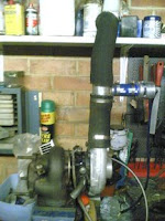
With the turbo rebuilt i decided to cut the pipes to supply the air supply to pressure ducting and then to the pressure covers that where going to go over the Weber 40 IDF carburettors.

The process of building the turbo unit was going to be a slow one as finances fro this project where not in place and as most components where around £50.00 or above and their availability was nearly impossible to find. I new this was going to have to be revisited several times as an when I could purchase a part to add to the turbo unit.