Search This Blog

MOT failures,brakes and a stiff test station

5th April 2009
Finally March has passed and the problems of the month seem to be disappointing. It has been a harrowing month of family problems some still not resolved hopefully favourably by the end of this week.

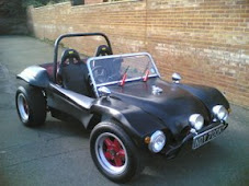
My buggy had also had an MOT failure. I had chosen the closest testing station Stiles Garage in Battle East Sussex which is a Ford dealer. It was also the Friday before Volksfest and I really wanted to have the buggy on the road.

The MOT test man pointed out 24 items that he felt in his opinion needed to be changed before he would pass an MOT on the car. To be honest some of these where very good finds the others seemed to be a little pedantic and ranged from bolts not protruding far enough from nyloc nuts to the wind screen wipers not laying flat on the body work, to the accelerator pedal being to close to the brake. I had a bigfoot accelerator pedal on the accelerator I think he didn't like it.

However the main failure was because of the rear disks. The rear disks did not seem to operate other than via the hand brake cable. Obviously this was very good to find and was worth the MOT test price alone.

He also did not like the noise that the exhaust was making stating it was obviously to loud lol. Funny I thought that was normal on a buggy. I had used a straight through exhaust on the temporary engine and realised I would have to create a baffle that would stop some of the noise escaping and offending people. A Friend suggested using a tail pipe from a beetle exhaust this was a pretty good idea as it had a baffle already built into it. The only problem was that the tail pipe and the exhaust where totally different sizes. Initially I tried securing the tail pipe into the exhaust with three opposing screws . This only slightly improved the noise level and it was obvious that the end around the baffle/tailpipe needed sealing. I thought I could wrap the tailpipe in exhaust wrap but unfortunately could not find enough material to wrap it up to the required size. Eventually a motor factor came up with a coupler that was a reduction pipe. Although this was not the correct size I worked out that it was the same size difference on both sides of the adapter. I sliced the adapter up its length and removed enough material to allow the pipe to fit. I remembered to use PI to work out the circumferences of the size i needed and the size of the existing pipe so that the difference between the two was what I removed. The adapter was then fastened on with exhaust clamps.

The end of March turned into a saga of fault finding on the buggy with the the hydraulic system being bleed and bleed and bleed with little success. I had read that the nipple should be facing up and not down so changed the callipers over from side to side. This also had the advantage of getting the handbrake cables further of the ground giving better road Clarence.

Unfortunately this did not resolve the problem I bought a Gunson pressure one man bleeding system that fitted onto the hydraulic reservoir. It pressurized the system 7up so that you could just bleed the fluid and the calliper nipple. This eventually gave some success however the rear brakes where now braking the pedal was traveling and hitting the bulk head which would be seen as another MOT failure.

I had spent the rest of March trying to think how to resolve this problem I placed threads on http://www.thesamba.com and on http://www.volkzone.co.uk . Eventually a member of the samba suggested that as my master cylinder was lower than my calipers I would need a residual pressure valve to keep the pressure within the caliper section up to 2lb. Now I was not aware by posting this onto volkzone that this would open a tin of worms. Several members of VZI said that this would not solve my problems other members suggested that my brake push rod length was the wrong length and might need adjusting. I ordered the residual 2lb wilwood valves and would have to try them when they turned up two days later. These promised to eliminate excessive pedal travel. I also managed to remember that these items needed a special adapter to connect them to the 10mm copper pipework as they where a Jic thread and ordered the adapters at the same time. I would also need to make up new hydraulic lines to connect to the valves. The lines would need to be 500mm long with two concave 10mm male connectors. In the middle 170mm from one end I would need to have convex female adapters. Bearing in mind the valve was 70mm long this would give me two lines one 170mm and one 260mm per side.

Later today i made another trip down to the garage and spent some time looking over the whole hydraulic system with a good friend and buggy enthusiast John. I had decided before coming that I wanted to check the brake pedal position something which was often overlooked when changing the master cylinder or removing and refitting the pedal set.The pedal was supposed to travel up to 3mm before hitting the piston in the master cylinder. Mine was over 15mm and once it was reset the pedal started to react better if not totally correct. A drip was noticed on one of the flexi-joints on the rear A-arm tightening this made the pedal movement a little better. I think the real change will be made only by the residual valves that i currently have on order and my hydraulic lines have been made up. My MOT retest was looming and I was not going to have time to fit the residual valves before the retest. The only question was would it pass or fail?

Super Flow Heads

12th March 2009.

I have been looking for some new 94mm heads for my new engine build for some time. Eventually after a long time some had turned up on eBay and they where wonderful 94mm Superflow heads tweaked and generally had everything known to an engineer done to them. Having blown my budget on a crankshaft and h-Beams I was not in a position to buy them and tried to broker a deal with him paying him payments he never accepted my offer and sold them at a lower price than I had offered him. I was gutted.

VZI to the rescue. Feeling at a loss for what to do as this had been the next vital part i needed a member of Vzi had noticed my thread and luckily had another set stored in his garage. After some discussion It was agreed that I could secure the purchase with £100.00 and pay the rest on collection. He sent me some pictures through vzi I could not believe my luck.

I havent mannaged to speak to the seller yet as I had lost my internet connection and his number I hope he will see this an give me a message.

Mad March affairs


9th March 2009
The start of this month has been utter madness my buggy has been off road for some months and this has only been reiterated in my head by DVLA sending out a tax reminder. This month is going to be utter madness. With my new engine still in dry dock on the living room table in boxes. The past winter months have bought an appathy in my head about the time I have spent in search of this new engine. My original estimates of the cost of this rebuild have been re worked out time and time again the high dollar price has caused prices to sore. With this said I have to look harder for parts and have been in search of some super flow heads. The first set I found I lost due to a ebay failure .Luckily I was approached by another Vzi member who offered me a similar deal. I am hoping this will be more fruitful. I have also decided to sell some of my old engine components and I hope they will be well loved as they have been on my buggy.

In the meantime i have had my case bead blasted and it has returned to me in a wonderful condition. I still need to have some engineering work done on the case. I hope the engineering work will be successful and will happen after I have aquired the heads.

In the meantime MOT and taxation looms at the end of March and I have a couple of issues outstanding before the buggy will be ready for an MOT. The first being the holes I had cut for the Drag bar that would need to be fibreglassed.

I decieded to use polymer fibreglass from a modelk shop instead of the usual kits that is sold in the garages in my area. This is a higher quality product and gives a longer cure time so it can be worked to provide a better fit. I made peices of card board to fit the holes and coaded the surface of the card with some household wax polish the hard block type. The cardboard was then mated with the body work so as to provide a framework for the fibreglass to sit against. I was careful to try and match the battery box indent that was on the other side of the car . The result is shown in the photograph. It hasnt been cleaned up as get and the underside has also not been fibre glassed. I am wonering whether the hole body needs to come of to do this and If it does I want to then seal the inside of the body work with a stiple effect. In the meantime its been sealed and should now go through an MOT.

The Aftermath and a new year

16th February 2009

The new year is here and its taken me a month to recover from the expense and Christmas fun and frivolities. I haven't done much in the garage over the last month as the snow, rain and generally crap weather has kept me inside.

My new engine is still in bits and is slowly taking up much more space in the corner of my living room in boxes. In January I picked up a new Crankshaft a Empi 78mm forged balanced crank. This came from Stateside Tuning along with the CB H-Beam 5.5 professional Rods . I wass not a great fan of Empi like most enthusiasts as they tend to have made some bad marketing choices. I came by the Empi Crankshaft after a great deal of discussion. It was pointed out to me that a good reason that some Crank suppliers used nitriding to put a hard coating on a crank when the material it was made from was not as hard as it could be. This in realiy seems very obvious and as the engine builder the information came from also balanced cranks I could see his reasoning as if the Nitride was only only a few micrions thick then it would be machined off very easily.

The CB H-Beam rods are just to good to be true they are exceptionally well made and seem to be well balanced from the box.

I have also been busy trying to track down other engine parts and have been doings some research on getting my Crankcase shuttle pinned.

Christmas 2008

12th December 2008.

Christmas and the bad weather that usually comes with it is arriving fast. This year I have managed to do a lot of work to my FibreFab SWB Rat. I have changed the rear suspension substantially to an IRS type that places the rear wheels firmly on the ground. This has improved the grip of the rear wheels and the buggy now feels like its running on rails. I have also managed to fit a rear disk conversion that has increased the stopping performance of the car. Unfortunately this year has brought a lot of engine problems that have made me fit a surrogate engine into the car whilst I build a new engine. This has been further troubled by finding someone who can line bore my new case ready for a new high performance crankshaft. I have now found a company that can line bore the case and they are based in Biggin Hill :

Baldyne Aviation Traders Engineer

Site 500, Biggin Hill Civil Airport, Biggin Hill,
Westerham, Kent TN16 3BN
Tel: 01959 540205

Classification: Car Engine Tuning & Conversion

They have assured me that they can still do the engine line boring and I am hoping to get the case to them in early January as I am committed to building my new engine next year after the Christmas and New Year fever has dissipated.

I want to finish wishing my readers a very happy Christmas and a happy New Year.

Installing a CSP Torque bar

31st October 2008

After modifying the bodywork of the car during the installation of the IRS components in preparation for allowing the A-arms to rise and have enough clearance I had decided to cut the body work high enough for the CSP bars to fit. The main reason for this was I was trying to stiffen up the rear suspension. The IRS fitting process meant that the Frame Horns had to be heated an bent to accomodate the drive shafts. This took some strength out of the Frame Horns and the CSP Torque kit would imrove this ensuring the floating Frame horns where locked into the rest of the chassis.

I had detailed the body work that needed cutting in a previous article and will not cover it again in this article. The main reason for the body removal was to eliminate a portion of the tyre well that came into the area the CSB Torque bars will fit into. This problem is only associated with my style of fibreglass bodywork and is not neccessary if you are using the standard beetle body.

After cutting the body work down I found that it was very difficult to get hold of the CSP Torque Bar kit. I did not want to import a new one from CSP as this was quite expensive and had luckily found one on eBay only to find that the seller was not really interested in selling it and was wasting every ones time by shilling the bids at the last moment so unfortunately I had to let that one go. A month later I had been watching eBay and all of the usual sale sites for some time when I saw the CSP kit above advertised. I secured it along with the rear gearbox mount. It was in excellent condition and all the welding work had been done and the mounting plates had been anodised in a gold zinc coating. This did not appear to be paint so I presumed it must have been plated.

The installation of this Torque bar kit is fairly straight forward the welding that is usually needed for this installation is detailed here: http://www.csp-shop.de/technik/pdf/deeng/20917.pdf You can see that the three bars triangulate the frame horns which support the gearbox cradle significantly reducing the flex that gets put into them from a high performance engine. The bars being made from Aircraft grade aluminium make the adjustable bars are very strong.

The rear cradle that supports the engine and gearbox is securely bolted to the frame horns by two large 36mm fine threaded bolts. They can really only be got at easily with the engine removed from the car. Considering this is a simple process of disconnecting the throttle cable and then undoing the four bolts, this is where we will start in my installation of the welded torque bar.

With the engine bolts removed and the throttle released the engine will sit on a jack above a plank of wood. This will hold the engine whilst it is still located on the final gearbox drive shaft. Be advised it safer for two people to help removing the engine. The engine can be slowly drawn and wiggled backwards off the final drive shaft in the gearbox until it becomes disengaged. The engine will then be solely supported by the jack and it should be slowly lowered to the ground with the engine nearer the ground. Ask your friend who has been helping you stabilise the engine on the way down to help you lift it from the jack onto another plank of wood. This should be easily accomplished but ensure if you are following this that you use the proper lifting techniques so not to strain your back. The engine long block should now be removed exposing the gearbox.

The gearbox is mounted between the rear frame horns inside the bell housing at the bottom where it meets the cradle there are two bolts that hold the gearbox rubber mounts to the gearbox. Undo these and secure the bolts and washers for later use.You will now need to place a jack under your gearbox to support it . Again place a piece of wood between the gearbox and jack to prevent damage. Ensure the jack is biased towards the rear of the gearbox near the bell housing . With the jack in position you will need to remove the lower rubber gearbox mounts on one side of the gearbox. This will allow the gearbox to be lifted out. Use the jack to raise the gearbox out of its cradle.

The gearbox should now be disconnected from the cradle and the cradle can be removed by undoing the two large 36mm bolts that hold it onto the frame horns. You will need considerable force to undo these bolts. Use penetrating fluid like plus gas to soak the bolts for a few hours before you proceed. If your lock the you will already have a long bar that you can use as an extension to your socket set . you will need at least three foot or a metre of something like scaffold pole or if tour lucky an air powered impact wrench. With the cradle free from the frame horns you can start re-assembly with the new cradle. Ensure that you re grease both the threads in the frame horns before you bolt on the cradle. If you had your torque kit bought as a kit that you can assemble You will have two holes on each side of the cradle that take the mounts for the diagonals. These bolt on with the Allen bolts supplied. If you are having to make your mounts follow the CSP article to locate them in the correct axis. Replacing the gearbox into the cradle is the reverse of the removal process. You can bolt one or both of the rubber gearbox mounts on the side(s) of the bell housing. Then lower the gearbox back onto the new cradle.

The top mounts for the Torque bar are located of the suspension damper arm. To fit them you must removed the top damper mount. To access this you will find it easier to remove the wheel on the side you are working on. With the first wheel removed you should easily be able to find the damper and the retaining bolt at the top. The suspension system is under load and although you can remove the nut from the bolt you will not be able to remove the bolt without remove in the load from the torsion bars that is applied to the swing arm. You can buy a tool from VW heritage to pull the spring plate upwards although this is fairly expensive and is not used very often. I have found that you can use good quality luggage straps to do the same job. The luggage straps have locks on them that allow you to wind up the strap under load. If you are buying these get ones bigger than an inch in size with metal buckles. Loop the strap over the arm and back around the spring plate you should be able to ratchet the strap up to pull the spring plate up. You only need to achieve a few mm as this will allow the top damper bolt to be able to be slid out and the new longer one slid in its place. The damper can then be slid back onto the new bolt. The top mount can then be slid onto the bolt and the whole assembly can be bolted up. If you are not using prewelded assemblies then you will have to just pop on the bushing and follow the CSP installation instructions to weld the mounting tabs in the correct axis. This can then be repeated for both sides. It is easier to hold the car on axle stands whilst you are removing the wheels this allows you to remove both wheels and work without having to put on a wheel and then jack up and remove the other. With the mounts in place the bars can be attached using the supplied Allen bolts . Beware if you have wound out the threads on the bars that these are handed and are not reversible.