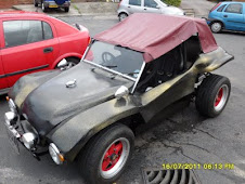
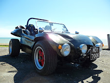
Turbo Induction .
19th December 2007
After mounting the turbo onto the car for the first time , the reality of the rest of the components that I needed to obtain started to dawn on me.
I thought my original budget of £500.00 to add the turbo would have been enough to get my turbo working. Now at this stage having the turbo mounted and the first section of the turbo system made. I could see that I was already over budget at £550.00. I had to make a decision about whether to go forward or to try and fit together what I had. I spent some time working out the cost of buying pressure caps for my IDF carbs and running the turbo through the carbs instead of my original plan to build a custom intake manifold. My Carburetors had been second hand and had come from Texas , so I was unsure of their origin and further more not sure they would be able to take the extra boost pressure from the turbo. My worries where that the throttle rods where not sealed for turbo use and would leak petrol. This was a very serious problem as although the carburetors could be made to work with the turbo the cost of this was looking more than $500.00 . I estimated that to get this stage working that it would cost in the region of another £500.00, although doing this would get me some experience in running the turbo I decided that It was fool hardy to spend this money in a direction that I was going to use as a stop gap to the fully turbo'd injected engine.
I had been looking on eBay at the multitude of different induction kits that there is on the market. It seems that when you buy one of these components you must know the car that it is being fitted onto. This is a bit of a problem , when you are building your own. I soon realized that most of these induction kits where in the region of £80.00 - £150.00. This was not something that my budget could afford at this present time.
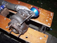
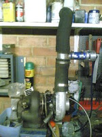
Luckily I had been talking to a friend about my dilemma of which direction to take my turbo and he had said that he had seen an induction system sitting on the shelf of my local breakers Yard 'Ripleys'. The following morning I went down to the breakers yard and was happy to find that they had the kit and they only wanted £15.00 for it including the AMF sensor. This was a result as the unit turned out to be Piper X from a Renault Saxo Turbo. I fitted the induction kit to the turbo and realised that I would need some more Samco hose to ensure it did not come off.
I ordered the tube from Demon tweaks and would have to wait till after Christmas to receive it.
I had a telephone call from Demon Tweaks stating there was a problem with my order. Unfortunately I have not been able to find out what this problem is as Christmas 2007 is nearly on top of us.
I want to wish my readers a very merry Christmas and a happy new year 2008.
Turbo Exhaust Inlet manifold - part three
17th December 2007
With the to parts tacked and then bolted on to the exhaust , with an small engineering level I was able to see that the flange was pretty much level and with the turbo attached temporally, you could see that that the turbo kit sat quite neatly on the back of the buggy.
I removed the turbo and unbolted the adapter and took it back to Philcox to have the flange welded in its final position.
Whilst the adapter was welded I returned home to find that the oil adapter T pieces I had ordered had turned up. I decided to see if this would connect up to the braided cosworth line that had come with the t3 turbo as the oil line feed. With the 1/8"bsp to 1/4" bsp adapter that came with the turbo I was able to connect up the oil line and screw in the oil pressure sender. I ensured that all the lines where jointed with oil proof thread lock.
I used a brass 1/4"bsp screw cap to seal of the oil line. The engine could now be turned over to test the oil line. The line pressured up without leak.
Labels:
adapter,
PiperXross,
Turbo
Turbo Exhaust Inlet manifold - part two
6th December 2007
My visit to Philcox had been successful and the old flange had been successfully removed. Philcox had suggested that the triangular flange should have been welded on the other side of the flange as was consistent with traditional methods of exhaust manufacture. They cut a new flange from stainless steel and ensured that the hole in the centre of the flange allowed the pipework to fit snugly inside. They used a plasma torch to cut around the gasket which would be cleaned up after the position of the flange had been ascertained and tacked, re-checked and then finally welded in position. I was very pleased with the job that they had done so far and it was obvious that the work they had done looked no longer like my own and more like that done by a professional company, something the previous company that worked on this item failed to realize. When you pay for a professional job, it should be just that, not something that you could have done at home with a MiG welder and some stainless steel MiG wire.
I would need to mark the flange position with a level and ensure the turbo bracket was in the correct position. Once this had been established, I would be able to return the two parts to have them tacked up.
With the two parts marked up with a pencil it was going to be a couple of days til the two parts could be tacked together.
I had been ordering some oil line parts for the oil feed for the turbo and received some of the parts only to find that they where the wrong size. I had ordered a 1/8bsp to 4-N adapter thinking that the 4-N was the size of the Goodridge Ford Cosworth oil line. Unfortunately this was not only to Small but had the curve on the thread top convex instead of concave. I learnt something today all bsp fittings have concave tops to the threads. I ordered the new adapter the 1/8bsp to 1/4bsp adapter and hoped this would be the correct one as these threaded fitting are very difficult to match up.
Turbo Exhaust inlet manifold - part one
30th Nov 2007.
This was the first attempt , the second was no nearer. It was time to change the company i was using to make it. Stainless is obviously slippery to weld.
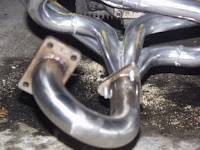
After getting a few quotes for the fabrication of this item I unfortunately went with the company that I thought would be the best and not based on cost of the manifold being made. This unfortunately was to be not a good idea as for the first time I had had something fabricated externally the company produced a piece of work which was unsatisfactory and not of good workmanship. As you can see from the picture the manifold was not vertical with the garret manifold not horizontal either. The second attempt when returning the manifold to the fist company produced not much better results. The manifold still placed the Garret about 20-25 degrees out and the horizontal measurement of the top of the garret flange did not read on my gauge. The Triangular flange had been skewed when it was welded to the pipe and was not horizontal with the tube. The finish was still no better.
Fortunately I am in the lucky position of having another company nearby Philcox's of Catsfield. Look them up on yell.co.uk, I am sure you'll be happy. They where more than happy to take the flange of from the inlet manifold and fabricate a new one that was going to be welded properly to the tubing. They also offered solution for the missing studs in the turbo flange they offered to weld in 10mm studs. I would need to return to pick up the manifold in two pieces to mark the upright position of the top flange.
I asked if I could have the triangular manifold cut of having to have it shortened by an inch and the 10mm studs inserted. When I asked if they would keep the old flange for me. I was asked if I wanted it for sentimental reasons, I said no , he asked if I was going to send it to the first company as a memento or a Christmas present. I conceded that it would make a novel Christmas present as a desk pen holder, LOL .
Garret Turbo Exhaust
14th November 2007
My Cosworth Turbo 2WD Stainless front section finally turned up much to the embarrassment of the postman trying to get this through the letter box to no avail.
I was very pleased with this item as I picked it up from eBay and to be honest this item was possibly the cheapest part I have purchased.
The exhaust I was planning would only need the front end of this exhaust section. When choosing your exhaust it is important to ensure that it comes from the car that the turbo came from. The reason for this is that the Garrett T3 unit comes with an assortment of different exhaust turbine sections to fit different exhaust.
I took the exhaust to a friends workshop to get it cut as cutting exhaust tubing to leave a square edge is notoriously difficult. My friend had a bench with a motorised hack saw that could hold the exhaust squarely in to cut it. I tried to use cleaning compounds to clean up the exhaust , but nothing seemed to budge the grime.
Luckily I had found a metal surface specialist company that would clean the exhaust with a glass bead blasting system, and would be able to then clean and polish the exhaust to a high luster. The results speak for themselves.
The turbo unit was nearly ready to go on the car. I only needed a few items left to get the lambda sensor, which was a V90HF9F472AA Cosworth Sapphire 4x4 Lambda Sensor these usually go for about £50 and I was hoping I could find one through an auction service cheaper. I would also need to purchase an induction kit for the turbo that would also required to be fitted with an air flow mass meter. Both of these senders would be needed for the Megasquirt ignition system that I still needed to source and build.
The next item that I needed to manufacture was the stainless steel section that would attach the Garret Turbo to my ceramic exhaust. I have been told this has to be stainless due to the high temperatures reached in the turbo. I had purchased a Turbo installation kit which contained studs and gaskets for the T3. I needed to locate the triangular 60mm gasket to join the exhaust. My plan was to make a u shape that would have to manifolds on each end. This would put the turbo up above and behind the exhaust in the same orientation that it came out of the Cosworth. I would need to find a company that would mill the flanges and be able to stainless steel weld them onto the manifolds. I had contacted one company and they had quoted me around £100.00 to build the adapter from scratch . The cost of this manufacture was high as the current stainless steel prices were very high making fabrication costs dear.
Christmas was coming at full speed and I was not sure whether I could spare this money before Christmas.
Posted by
Martin
What have you to say?
2 VIEWERS CLICKED HERE TO COMMENT ON THIS POST. ADD YOUR COMMENT.
Turbo Spooling
11th November 2007.
After a mournful start to the day and a number of interesting thoughts conjured up by the bishop of our church , whilst visiting with my daughter who is in Rainbows. I ventured back to the garage.
I noticed that the actuator valve was not closing entirely and remembered reading an article on the Internet which suggested winding back the actuator arm turnbuckle five turns to obtain the best boost with the Collins actuator and to ensure that the valve was clamped shut. I had not yet managed to acquire the silicon hose to connect the actuator to the compressor housing nor had I managed to buy the correct turbo housing brass tail which was a T piece allowing a boost gauge to be fitted.
Whilst in the garage I decided to see if the Turbo would spool up If I held the turbo inlet to the exhaust. I wanted to see if the turbine would spool up before I released the funds to build the stainless exhaust to turbo manifold as this was going to be fabricated by a company that could fabricate, weld and mill stainless.
I started the engine and held the turbo flange against the exhaust flume. At tick over nothing moved. I reved the engine and watched to see if the compressor turbine spun up. It spun up very easily. I quickly removed the turbo from the exhaust flow as I had not plumbed the oil feed or the oil return to keep the bearings lubricated.
This was a major part of the testing for the turbo as I was unsure that the RS Cosworth T3 could be driven by the 1641 lump. I had intentionally chosen a small compressor to allow it to spool up at low reves.
The next phase was to have the stainless exhaust union made to allow the turbo unit to be bolted to the exhaust.
I had purchased a T piece for the oil supply from the pressure gauge output although I would have to get taps and dies to re-thread this to 10mm 1.0mm pitch as I had bought a T piece with 1/8 bsp on each thread.
I also had just purchased a stainless exhaust from a cosworth 4x4 that i was intending to shorten an re-bend to create a screamer type pipe with a park arrestor on it. I would have to receive the exhaust before I new for sure what size pipework it used as I was not sure if it was 2" or 3" pipe.
Christmas was approaching at great speed and I was going to concerate on my family christmas for the next couple of weeks or months.
Hopefully some of the new parts I have ordered would turn up and the exhaust manfold would be made and delivered.
Labels:
Spark Arrestor,
Turbo
Fitting a Collins Turbo Actuator
10th November 2007
Whilst acquiring bits for the turbo accessory bits i needed I acquired a Collins Group A -31 Actuator which was supposed to be compatible with my T3 Turbo which came from a Ford Cosworth lump.
I soon realised that my actuator had a straight arm. This was annoying, as my bracket that came with my turbo positioned the actuator too high and looked as if it required an arm with a bend in it. This was particularly odd as it was sold with a straight arm actuator fitted. I now believe the reason this worked before was that the compressor output on the side of the turbo must have been directed in another direction. Additionally you will notice that the actuator was second hand and someone has welded the nut onto the thread. This is supposed to be a locking nut so I could not imagine why this had been done. It was lucky I had a nut splitter. This made short work of the nut and it came off easily, otherwise I would have to locate a replacement.
I decided that as the turbo components where able to get very hot that I would use stainless steel sheet to make the bracket. Luckily I have a scrap merchant that i have used for some years who is happy to sell me scrap stainless steel. Firstly I removed one of the compressor securing plates and drew around it on a piece of card. I left a large area of card on the opposite side of this so that i could shape it into a bracket. I bolted on the card board and set the actuator where i wanted it to go. I bent the card back so that i could mark the position of the bolts that protrude from the actuator. This gave me a rough template for the compressor housing bolts and their relation to the actuator mountings. From this I was able to use the old bracket to transfer the other holes that the actuator uses.
I was then able to draw around the holes to make a bracket shape. This was the stuck onto the stainless with paper glue.The holes could then be drilled in the stainless where they where marked on the paper template. Drilling this required a very slow drill speed as it is easy to break,blunt or snap a drill bit when drilling stainless. I am pleased to say that my Starrett 3/4" hole saw and arbour drilled through the stainless also without any sign of problems.
The next job was to start cutting the the bracket out by cutting around the paper template. I used an angle grinder for this although a plasma cutter would have been faster. You must remember to keep the template wet otherwise it will burn from the heat of the cutting process.
Once the template had been roughly cut around I used a clamp and a large 4x4 post to clamp it to so that it could be worked on. The metal was soon removed from around the template by filing it away with a coarse metal work file. Once the bracket had been cleaned up it could be bent to shape. This required a large vice and a larger hammer. Bending metal always leaves small marks on the metal and I used a sanding disc in the angle grinder to clean them off. Warning Don't pick the bracket up after sanding, It gets very hot.
The bracket was fitted to the turbo to see if the angles to which the bracket had been bent where suitable for the actuator to fit and reach the waste gate crank without bending the arm in the actuator head. The first trial showed that the bracket was still about 10 degrees out.
Once the bracket had been re-bent it was fitted onto the turbo to check everything fitted OK. The sanding process leaves striation lines on the surface of the stainless. I used some copper saucepan base cleaner to remove this giving a better finish to the metal work.
The Actuator fitted onto the turbo quite nicely and when making the bracket I had made sure that the bracket would not foul anything else. Especially as the oil return was quite close to the bracket.
You can see in the picture above I have replaced the compressor bolts with Allen bolts and sealed the water unions with 18mm x1.5mm pitch Allen grub screws.
Posted by
Martin
What have you to say?
1 VIEWER CLICKED HERE TO COMMENT ON THIS POST. ADD YOUR COMMENT.
Labels:
Collins Actuator,
Turbo
Garrett Turbo T3 assembly.
4th October 2007
When you buy a turbo unit second hand with the intention of using it for a project you are very lucky if you get one in good condition. Usually as we have already seen you have to purchase a tturbo repair kit and fit this to the turbo to make it functional. In addition to this there is also a large amount of extra componants that you need to put onto the unit to get it to function. This is something most suppliers neglect as they could normally assume that you are just replacing a unit with another. Normally you can bolt on your old fittings so this is not a problem. In my case I have to locate new parts: Lamda Sensor; Air Mass Flow Sensor; actuator and water union block off bolts.
Generally most of these componants are readily available and are easily found on eBay or similar auction house.
I located bolts to seal up the water unions after a days worth of surfing . Made from stainless these are quite an expensive item to purchase.
http://www.a2stainless.co.uk/M18-x-1-50-x-12mm-Pipe-Plug-DIN-908-A4-70_AICFP.aspx
INCORRECT "I also needed to aquire an 1/8th inch connector with –4AN flange fitting to make up my oil feeds. "
Turbo Exhaust
27th October 2007
After a long serious ton of improvements its was now time to consider the project that I put on hold in March earlier this year. During the year I had been searching in vain for an exhaust system that I could mount the Garret Turbo T3 onto. the problems seem to be over heating cylinder 4 . Even to close engine proximity with a normal type of 4 into one system. Heat being the worst problem in a Garret this really a problem for an air flowed cooled engines as most modern turbos including the T3 use water as an additional coolant. I thought that the best option was to keep the turbo the furthest away I could from the engine by using a good quality drag exhaust. Luckily while surfing on eBay I found a new friend living in the next village that specialises in drag racing cars and fortunately for me he had a 1 1/2 " drag exhaust for sale. A deal was soon concluded and I was soon in possession of this fine ceramic coated exhaust.
I removed my Thunderbird Dual Canons and after polishing them and shedding a few tears put them on eBay for sale. The Cannons had been a good investment and they produced a lovely sound. I new that it would be doubtful I would ever get another set like this again as the new versions where thin metal and poor chrome in quality to the set I had purchased for the buggy some time ago.
I have to give credit here to my partner Cathy who's labours in the afternoon with SOLVOL AUTOSOL brought these exhausts back to their former glory. It was going to be a while before the buggy was back on the road and I knew I would have fond memories of the sound that this exhaust gave.
The new drag exhaust was spectacular although it would need coercing into the car. First looks, gave me a fright as it looked as if half the engine would have to come of to allow it to fit. I had made some alterations to the tin wear at the bottom of the cylinders that allowed the air flow to totally encompass the cylinder heads. Unfortunately the bottom exhausts going to 1 and 3 went straight through the centre of the cylinders close under the push rod tubes. This meant that I would have to dissemble the tin wear additions. The screws are well hidden and this took a lot longer than I imagined. I also had not realised that the fan control thermostat was in the way of the new pipe running to cylinder #1. So this had to be removed also. On fitting the new exhaust system it was apparent that my rear cage was going to be incompletely in the wrong place, and it would need to be removed and extended when the engine dimensions had been altered and their sizes where all known. TIP when you put your rear cage on. ensure your bolts can be removed with the car body in place. All but one of my bolts where fine and this would involve putting the car on a ramp to get the last bolt out with either an angle grinder or heavy duty bolt croppers. The side elevation of the engine had now changed beyond all fathomable appearances. The Cannons had covered up the side of the engine for so long it that it was going to be lovely to have access to the valve timing and cylinder heads once more.
I was going to have to design a mount for the turbo that would come of the lower flange of the exhaust. After a serious amount of thought discussion and debate . I decided that it would be best to come out from the exhaust and rotate through a full 360 degrees before I came into the turbo. This would put the turbo orientation correct for the exhaust exiting the drivers side of the vehicle and the regulator valve assembly for the turbo pressure still being able to be used.
I had not yet decided whether to fit another blow of valve on the exhaust side. I would need to source the parts I needed and weld them up prior to this becoming an urgent decision.
Labels:
Exhaust,
Thunderbird,
Turbo
Side Impact Bars - part three
29th August 2007
I Finally had enough time to get the welding gear outside and the house. The weather being the hardest thing was great and I bought the buggy down to the house with both impact bars bolted in there respective positions ready for welding.
Unfortunately my generator was not capable of delivering peak voltages that the welder needed so I could not do this work in the garage as it has no constant power supply.
The piece that I needed to weld was sitting on top of the body works fiberglass perimeter and I was unsure weather welding or tacking the pieces would cause the fiberglass to burn. I ran a bucket of water and placed a cloth in it just in case. The cloth would also be useful to quench the metal should they get too hot.
I started with the passenger side as I would not have to navigate past the steering column on the first weld and hoped I could gain experience, that would help me on the other side. I placed the two pieces of plumbing matting that I had found on the wall of the body to shield it from the heat. I managed to tack the two pieces together fairly easily. The join seemed fairly good as I was able to unbolt and remove the two pieces which where now one. Once I had removed the part I was able to weld the two items securely all the way round. I remembered my father telling me that you test a good weld by tapping the different parts of the same object and listen to the ring it gives out. The tone should be the same wherever you tap, indicating the item is one solid piece.
The driver side was much the same although the restricted access made the taking process a little difficult. I managed to remove the joined pieces and again successfully welded them.
Once the pieces had cooled. I bolted them back in and cleared up wanting to take the car out for a run to see if it had made and difference to the cars handling.
Straight away the buggy seemed stiffer and seemed to handle more positively on the road. I was surprised that this had improved the handling and am now wondering what else I can find that will improve the cars handling still further. bearing mind I was planning to fit a turbo + injection system to the car any increase in the cars handling on the road would be beneficial.
I am planning to get the new bars zinc plated , but I will have to contact my metal plater to see how much this will cost and when it can be done.
All in all, my side impact bars seemed to be a success.
Labels:
Roll Bar,
Side Impact Bars
Side Impact Bars - part two
28th August 2007
After taking some time to think through the position and placement of my newly acquired tubing. i set to and started of by rounding off the flattened end , which had hard right angle corners. This then allowed the bar to be placed in position to check its position in the car.
I drilled a hole to allow the Roll Bar hoop lugs to take a M12 bolt through the lug and through the new bar (pictured left).
Three of the perimeter bolts where then removed nearest the front of the car so that I could place the position of the bar in its actual position. I noticed that the cut on the bottom of the tube was not allowing the bar to sit squarely on it. I marked this with chalk. The bar was removed and i used an angle grinder to re cut the angle.
I drilled the holes in the bottom plate to allow the perimeter bolts to be passed back through. This stopped the plate from sliding about . I used a piece of wood to push the tube into position on the plate. I would have to tack weld it in position. I was not sure how to best protect the fibreglass whilst this was done so decided it would be best to make up the other side and weld them both at the same time. Unfortunately It was dark and nighttime again upon me so I had to leave the welding and fitting of the other side to another day ...
To be continued.
Labels:
Roll Bar,
Side Impact Bars
Custom Side Impact Bars - part one
28th August 2007
After seeing several videos on Utube and reading about the accident on my beach buggy group. I decided that my Roll Bar hoop was simply not rigid enough to withstand my buggy flipping over.
I decided that I would have to reinforce it with a side bar diagonal that reached the perimeter bolts that held on the tub. I decided that the construction of this would need to be very strong and built with thick wall tubing that I would not be able to bend with traditional equipment. Luckily I had a tubing specialist company 'Anvil Tubing Ltd' in Sedlecome a short journey away.
After describing what I required they quickly used their tube bending heavy machinery to fabricate four sections of material. Two pieces of steel bar to go around the perimeter of the tub and another two sections of thick wall tubing to attach to the Roll bar and weld onto the perimeter bars. Obviously with the correct machinery this was a fairly simple job. The picture right illustrates the design of the side impact bars and shows the raw material before it was drilled or welded. I hoped that the design would also stiffen up the chassis and stop some of the flex that I was getting on bumpy ground.
I would need to remove the side pods to get access to the Roll Bar body bolt that I was hoping to fit the flattened section to. I would also need to remove the perimeter bolts and position and drill the assembly before it could be tacked together and then welded. I intended to have the items sand blasted and zinc flame coated as I had already done with the Roll Bar to prevent rust from gaining a hold.
To be continued.
Labels:
Roll Bar,
Side Impact Bars
Shakes, Shimies and steering
22nd August 2007
Having been driving the buggy around for a few weeks in the sunshine , when time permitted. I had noticed that the front wheels where wobbling at around 40mph. I thought this must be due to wheel balancing and booked in to have my front wheels balanced £10.00 later and whilst my front wheels where being put back on, the mechanic noticed my front wheels where moving alot and suggested either the problem was due to track rods being loose, or worn or the steering box was on the way out.
I took the buggy home and that evening had a look at the track rods. They where not in very good heart and seemed to be loose, so I decided to replace them all with new ones.
The track rod ends where held on with split pins and castle nuts. The new rod ends came with nyloc nuts and seemed like they would be easier to install. The first three ball joints the two outers and the driver side inner came out reasonably easily. The final one the inner passenger side gave considerable trouble. I tried initially to use a F wrench and a section of the trolley jack handle to wrench out the ball joint. Neither this nor heat or a combination of hitting or soaking the track rod end in WD40 helped.
I word to the wise.
I decided that a lunch break was called for and went shopping to see if I could find a ball joint splitter. Halfords provided the solution and I was soon back at it attacking the stubborn ball joint. Even with the Ball joint splitter it took an hour to get the track rod end out of the steering box arm.
Once I had the track rods out I measured them to ensure that when I replaced the new ends that the track rods remained the same length, hopefully ensuring that the tracking was OK.
Whilst I had the track rods out .I resprayed the track rods and cleaned them up. This was principally as I new the buggy would need to be tracked and if the rods where greased up and free this would make the job simpler.
I reassembled the track rods and placed them back into the car. I was unable to check the tracking by eye as it had become dark. I left this job until another day.
Fitting new hand brake cables
1st May 2007
The MOT behind me and with broken handbrake cables thanks to the gorilla testing the vehicle. When will they ever learn about VW Beetles and their derivatives.
I had used a conventional shortening cable kit for the job , which had pulled out from the shorteners even though I had used thread lock.
I had discovered some useful cable hardware from my local boat chandler and with the 3mm thimbles, cleats and clamps. I was intending to shorten the other end of the cable by using the thimble to replace the end that fits the lever inside the brake drum.
This solution seemed much easier to get a strong fixing with as the standard shortening kit used a small grub screw to fasten the cable in a threaded bolt.
The original hardware would run up to the hand brake and i proposed to shorten the cable in the drum and use the thimble and clamps (I had two versions) to loop the cable back into the same shape as the original. Although I have not seen this done before the same principle is used to fix main stays on boats. The main stay being the wires that hold up the mast. They take an enormous amount of strain as they can support two sails and a spinicker with the full force of a force three on them. I hope they will therefore be able to hold 620kg of beach buggy more effectively.
The handbrakes cables are fitted by removing the rear wheels and then the brake drums from each side of the car. This then gives access to the cables so that they can be removed from the drums and then once they are unbolted from the hand brake they will pull through out of the car.
I intended to fix the handbrake end of the cables in place and measure the cable lengths with the drum exposed. This solution seemed much simpler than trying to shorten the cables between the seats.
I tried shortening the cables with the fixings I had brought and found them very hard to use as they where very difficult to get the cable thimble in the correct position. I tried several times and failed with the handbrake cables being the wrong length. I came away and scratched my head and eventually found a ship chandlers workshop that put the thimble on the end and secure it with a crimped fixing in their machinery. The result of this was a very clean fixture. I measured my cable lengths initially as 136.5cm for the passenger side and 141cm for the drivers side. I took the cables and had them shortened. Unfortunately one side was still to long and I had to go and have it shortened and reduced in length from 141cm to 138cm. I was unable to get another handbrake cable for several days as the supplier I used was out of stock. I will have to write a new post when the passenger side cable comes in and can be fitted.
Cable lengths:
Passenger Side138cm
Drivers Side: 136.5cm
MOT test
16th April 2007
The day I had been dreading was here and I had previously booked an MOT with the most extensive tester in my area to ensure that my Beach Buggy was reliable and safe. The MOT station was a good 15mins drive away so I intended to have a nice drive down to the tester as there where some nice straight roads on route.
Although I was testing the Beach Buggy for road usage it was in no way finished as it still needed an interior and a good respray.
The morning of the test was a sunny one and I had time to look over the buggy to see if there was any problems that I had missed. I noticed that the side pods where a liittle wobbly on the rear of them so I bent some stainless up and made some small brackets which firmed the side pods up tremendously.
The MOT took and hour and I walked into the nearest town. On my return the buggy had failed on several points. I had not placed spilt pins in the steering assembly and the headlights where out of alignment.
I drove the buggy home and booked up a re-MOT the following week.
I had to admit defeat on the headlights and took the buggy into a garage to have the headlights adjusted.
The spilt pins was a 1hr each side to fit as the steering system had seized.
23rd April 2007
MOT passed with flying colours
Building a turbo engine part one
17th Mar 2007
The heart of a good turbo engine is its turbo. I had purchased a Ford RS2000 Garret T3 turbo unit from eBay some months earlier with an interest in the possibility of turboing my Beach Buggy. The Garret T3 had arrived some weeks later and it was clear that buying a turbo from eBay was not a god investment. Firstly the exhaust housing was cracked and secondly the bearings where completely shot.
Most people that know anything about car turbo parts will know that any part whatever it is will cost you at least £50.00. This can be anything as simple as a Samco hose made of a latex/silicon material to a simple repair kit.
I found a Garret T3 repair kit online and at the same time found a Bailey dump valve and some connecting tubing on EBay. I had left all this in the garage as I was in no hurry to rebuild the turbo as I had plenty other projects on the Buggy to keep me going.
The Garret T3 turbo is held together in there sections the exhaust housing, The main water/oil bearing block and the turbine housing. All three are held together in the same way. The real skill comes in getting the bolts out from the housings as the turbo unit runs at very high temperatures which seize the bolts in place. Obviously with this in mind a good blow torch and determination is needed to remove the bolts holding the rings that hold the three components together.
Once the securing rings around the turbine housing are removed the housing can be removed leaving the fan and bearing block exposed. The securing rings on the exhaust housing have to be undone in stages as the bolts will not come out all the way as they hit onto the bearing block. You need to twist the bearing block to rotate it so that all the bolts will come out. This took a vice and a hammer to release mine and the exhaust housing parted leaving the bearing block with two fans at each end. The fans are held onto a long shaft by a nut at the compressor end. This is torqued up to a very high torque and takes some getting undone. Once removed the spindle can be removed and the bearing block left .
The bearings are little brass rings on the T3 that are held in by circlips. It is important to ensure that the circlips sit in their grooves and to install the inside circlips on both sides before putting the bearing in followed by the securing circlip.
With the bearings installed and the other components that come with the bearing kit added the shaft can be reinstalled and torqued back up. I decided to grease the bearings with grease to ensure that they worked and had lubrication when the turbo was first fired up.
The rebuild of the turbo unit is exactly the reverse of dismantling it. The exhaust housing needs to be rotated on the bearing block to allow all the bolts to be inserted.
With the turbo rebuilt i decided to cut the pipes to supply the air supply to pressure ducting and then to the pressure covers that where going to go over the Weber 40 IDF carburettors.
The process of building the turbo unit was going to be a slow one as finances fro this project where not in place and as most components where around £50.00 or above and their availability was nearly impossible to find. I new this was going to have to be revisited several times as an when I could purchase a part to add to the turbo unit.
Solving the mystery of my engine madness
9th March 2007
The day had started badly with my engine valve re-tune not fully riding me of the problems of backfiring and popping that I had been plagued with since fitting the twin Weber 40IDF carburetors.
I was sure that there had to be a reason for the engine noises as the engine seemed to run much better when it was stationary. There had to be a loose component or something that was failing during acceleration. I considered the electrical system and was sure that the ignition system was solid as had already checked this out when I fitted the new spark plugs.
If the ignition system was OK this only left the fuel system. One possibility was that the fuel fuel reservoirs in the carburetter float chambers was not full enough and was moving whilst the car was accelerating. The problem with this was that I had already had the float levels set up by a specialist and new they where correct.
After eliminating everything else I was left with the fuel regulator which regulated the fuel supply to 4 psi. I removed the regulator from the fuel system fuel lines and tried again , giving the car a short run. To my amazement the problem had disappeared. It seems that my corroboration problems had been plagued by a bad regulator that I had bought from eBay. I was not sure if it was my mounting or adjustment as the regulator had no gauge. Either way my buggy sounding more like it should.
Tuning up - Adjusting my valves
8th March 1007
My engine had been coughing spluttering and backfiring for several months and my attempts to solve this by corroboration had not come to much fruitfulness.
I decided that as my cylinders #3/#4 were making a larger than normal tapping sound and it was also noticeable that the exhaust from these cylinders was considerably colder than cylinders #1/#2 that I should tune up my valves
The procedure for a valve tune-up is fairly simple as long as you have the area clean , the correct tools a feeler gauge; 13mm spanner; 19mm spanner and a large screwdriver and a smaller screwdriver.
Before starting I remembered to purchase some new cork gaskets for the valve covers and put my ground sheet down under the cylinders #1 and #2 . The first cylinder is easy to find as you can remove the top from the distributor and crank the generator nut with a 19mm spanner until the rotor arm points to the line on the perimeter of the distributor body. With this set the feeler gauge can be used to check or set the valve clearances for cylinder #1. I used the .008" and .006" blades from the feeler gauge to check that the adjustment between the rocker arm and the top of the valve stem was .006". By trapping the 0.06" blade between the adjuster and the stem and doing the adjuster up until you can just slide the .006" blade in and out with friction. It is possible to then do up the lock nut and check you have the correct setting by trying to insert the .008" blade. If this is successful and the .008" blade fits you have the wrong setting and must go back and try again with the 0.006" blade. This has to be repeated for the inlet valve and the exhaust valve.
The whole engine has to be moved backwards by 180 degrees so that cylinder #2 is in firing position. This can be accomplished by using the 19mm spanner to rotate the generator anti clockwise so that the large pulley on the crankshaft travels 180". Once done the valves for cylinder #2 can be set in the same manor as cylinder #1.
At this stage two cylinders have been adjusted and #3/#4 remain. You can keep rotating the engine by 180 degrees a further two times adjusting the valves on #3 and then #4.
Once completed you can replace the valve covers with the new gaskets that you have purchased earlier.
I started up my engine and was happy to see an improvement , however before long there was a slight metallic sound coming from #3/#4. I shut the engine off immediately.
I presumed something had come loose...
I had to wait another 24 hrs to let the engine cool down and could not get back to remove the valve cover until the following morning. Once I had the valve cover removed it was clear what had happened. I had encountered some problems getting the valve cover on #3/#4 and had inadvertently knocked the retaining pin off the rocker assembly. I found the pin and three washers complete in the bottom of the cylinder head. Replacing them was fairly simple and the pin was a tight fit. I carefully replaced the valve cover after cleaning up the gasket and restarted the engine.
The engine fired up beautifully it sounded like it was running much better and producing more horsepower. I reved the engine and found a nice rich sound of power. I jumped in and backed the car out of the garage and put the buggy into first gear and pulled away. The engine started to pop and splutter and sounded like it was running unevenly.
This was very odd. I could run the engine stationary perfectly but could not drive the car without it spluttering and making awful noises.
I would have to have a rethink ...
Building A Compressor, My Clark Pioneer 100+ SIP HobbyAir 210
3rd March 2007My Clark Pioneer 100 compressor that I was kindly given by a friend as it did not work was only capable of 3.5cpf displacement as it ran at .6hp, this means that it would only run small air tools and the LVLP newer guns at 8Bar .
I had a SIP HobbyAir 210 1.5Hp compressor without a tank that was capable of 7.5 cfm output that I felt would give the compressor more power and would hopefully power the HVLP guns on the market as well.
I decided that I could mate the two compressors and started by removing the plastic cover of the SIP HobbyAir. This was easier said than done as the bolts holding on the cover where recessed into the plastic so far that I needed a box spanner to reach in far enough to get them undone. Eventually I found a suitable box spanner in one of my toolboxes and got the plastic lid off. The HobbyAir was similar in construction to the Clark model but a lot smaller and lighter. I presume this was due to the HobbyAir being newer. I removed the Clark compressor motor by undoing the housing bolts and then the air and power lines that can be accessed under the switch panel.
It looked as if the Hobby Air would fit in the cradle of the Pioneer base. It would not line up with the bolt holes but I soon created some new bolting positions and started to work on the wiring.
I figured it was best to marry up the wiring in such away that if the Hobby Air compressor would not work with the Clark tank that I could easily put the Clark compressor motor back on and rebuild the HobbyAir to get me back to what I started with.
The wiring was pretty easy and I managed to bend the air pipe so that it reached the output from the Hobby Air.
The pump power up.
The capacitor on this model was CBB60 a 25 uf EN600252-1 starter cap
I was hopefully now in the possession of a 7.5cm 8bar compressor. I could not run a long test as my 4 month old daughter was in bed. I would find out if my creation lived another day.
I would have to make a new cover for the compressor engine and fan another day.
R/H Sidepod Respray & Balancing the Carbs.
2nd March 2007
After fixing in the battery compartment I was starting to run out of critical potential fails that would stop me getting a MOT. I new that the engine was running badly and that the drivers side pod need to be blacked out as it was white. This was a fairly straightforward procedure which unfortunately needed a couple of warm days in succession to do as the temperature needed to rise for spraying.
I used black satin spray from a spray can on top of car primer. This provided a good coverage that I new would come of in the summer if my planned respray went ahead. The sunshine was lovely and I was waiting around for the side pod to dry sometime wishing all the time to go for a drive.
The side pod eventually dried and I had had the opportunity to fiddle with the carburetor balancing whilst I waited. I had managed to warm the car up to a good temperature and the work I had done previously on the linkage rods made it easy to get a good idle. The Buggy was starting to sound great. This made things worse as now I really wanted to go for a drive. I bolted on the side pod and ran the car around the garage complex . It was now pulling like it should and to be honest in all probability should pass an MOT. I new that this would be a while before I could get the buggy MOT'd as it needed to be weighed and I had to line this up with someone.
The pictures were taken on a mobile phone the day after the work was done they had to be taken inside the garage as it was raining and this is why the pictures are low quality.
I also had to arrange insurance and the three things needed a cash injection of around £200-00 before i could get the car on the road.
Building the battery fastening device.
25th Feb 2007.
OK before we start no Darth Vader or Daft Ader comments or wow that's an improvement. Caught in the act !
The day before I had spent the day looking around the buggy looking for jobs that needed to be completed before the M.O.T. This culminated with the front number plate being fastened to the bumper with self tapping screws and the formulation of the idea of a way to hold the battery in place as I had been recently told that the MOT regulation requires that the battery be able to stay in position with the vehicle upside down. I decided to sketch out some ideas that could be constructed from some angle iron. The premis was simple as i needed to have a bar across the battery and then some screws down each end that would hook into a base. The base could be constructed from a frame welded from 1" angle iron, the top from 1/2 angle iron and the securing bolts from 6mm steel rod.
I cut the 1" angle iron with an angle grinder so that I had one of the angles removed and a flat piece of steel about 6" long. The end I made up from 5" of angle iron and drilled a hole in the centre to take the bolt. I new this would needing welding and only had my trusty Sealey Mig 100XT to weld it as my Arc welder was at my fathers. I had not used the Mig for a while so as with all Mig welders it needed a clean up before I attempted to weld with it. The welding material was rusty and this had to be removed until clean material was available and the tensioner had to be adjusted. You should never attempt to weld with a MIG welder that has rusty wire as it can block up the welder and causes the mechanism to slip as the rust acts as a lubricant.
I welded the framework up easily welding both sides of the frame to provide a good weld. This made a nice solid base and I finished the welding on the first end and was soon onto the other end. I am glad I cleaned up the MIG as it was performing beautifully and creating good solid welds on the Angle Iron. You can see in the picture opposite that the base of the battery compartment was taking shape. I cleaned the welds up with my Angle Grinder and packed the welding equipment away and returned to the garage.
Now you may ask why I welded at my house when most of you are aware that I have a 2.7KW Honda Generator, the trouble is the MIG seems to use about 2.8kw at peak and the welder trips out. I will have to service the generator at some point and try this again as most information on the net says this combination should work.
In the garage I heated up the rod ends and bent them over in a vice. I took the battery out of the buggy and placed it on top of my frame. This gave me a height that my screws would have to be. I cut the rod down to this length plus one inch and then tapped tapped a thread on each with a 6mm metric die. The bar was cut to length and the rods could be inserted. I drilled the base so that it could be fixed to the fibre glass.
The frame looked great and I took it back to the house with the in tension of taking it to my Zinc plater AC Blastings, who provide a hot Zinc spray process. This would take a while and I intended to get it to them on Monday.
Another tunning attempt in the garage thwarted
18th Feb 2006
I returned to the garage after changing my carburetor linkage the following day. I was full of expectation as I hoped that if I could get the carburetors ticking over that tuning would also be possible. I opened up the garage and started up the buggy and was pleased to hear the most wonderful puring noise at 900 r.p.m . One of my friends John had come over with his buggy and it was nice to show him my progress. A short demonstration ride , however brought to my attention another problem that was getting worse on a daily basis. My gear changes where becoming impossible and reverse was giving the most awful grinding noise.
I suspected this to be the clutch and hoped it was just the adjustment as I had about 3" on the pedal. I knew this procedure was fairly long winded as it involved removing one of the large rear wheels to gain access. The wheel came off fairly easily and gave access to the clutch lever under the body work. The cable had been shortened with a shortening kit and looked like it had worked loose. The nut that held the cable in place was loose and was not trapping the cable correctly. I took the shortening kit of and after lubricating it , checked to see if the nuts went up and down on the threads easily.
The shortening kit fitted back on to the cable easily I had bent the cable with two pairs of pliers the shortening kit sat in this new loop. I was able to tighten the nut onto the cables by holding the cable in the pliers whilst doing up the 19mm spanner. The shortening kit was then slotted back into the clutch arm and the butterfly nut was tightened down to allow 1/2 - 3/4" pedal travel.
I then had to replace the rear wheel. This is always a difficult task as it means the car must be jacked at exactly the right height to facilitate the wheel being aligned with the bolt threads. This took me over an hour to achieve and with having to lift the wheel a little to get one then all four nuts started. I tightened the bolts down hard and then took the car of the jack.
I needed to run the car out to straighten the suspension so the wheels settled back down. The clutch was working fine.
Unfortunately I had used up my petrol allowance for this week and therefore could not tune the tune the car I locked up and went home.
Another day with the linkage kit
17th Feb 2006
Today was a day of trial and tribulations and to be honest a day off trying to get the car to tick over at 900 r.p.m. The reason for this low rpm was because my gear box would not easily select reverse when the engine was reving. My Engine had been ticking over at 1200 r.p.m which was a little to fast and I had to bring it down.
I had previously improved the linkage kit by improving the amounts of thread on the adjusters so they had plenty of movement. This however was unable alone to get my r.p.m down. Despite making lots of adjustments the engine still settled after full throttle at the 1200 r.p.m spot. I decided that I needed to pull the linkage back to its stops with some heavier springs. The carburetter linkage bearing plates had a small hole that an extension spring could be positioned in. The right hand carburetor had a hole on the throttle leaver that the other end of the extension spring would fit into . This stiffened up the right hand side. The left did not have a hole so I removed the throttle leaver and drilled a 1/8 hole in it so that the spring would fit. With my new return mechanism in place I thought this would resolve the r.p.m problem , However I was to find that the car still reved at 1100 r.p.m.
I spent some time checking the linkage kit tightening it up so that I had very little movement in it at this point I noticed that the right hand carburetor was the point of trouble. It had a smaller throttle lever and this was not returning. It was late in the evening and I had to leave the problem for the moment as I had run the battery out starting and stopping the car the number of times that I had. I would have to return to this problem another day.
I decided to visit the garage later to pick up the battery to charge it properly. Whilst there I pondered the linkage some more the springs held the left hand side back against the stop and the left was just coming short. The result of this was the right hand carburettor was supplying more fuel at idle. I adjusted the rod so that it was shorter so it pulled up the distance I would have to return with the battery charged and see if this resolved the r.p.m problem but it looked promising.
Posted by
Martin
What have you to say?
1 VIEWER CLICKED HERE TO COMMENT ON THIS POST. ADD YOUR COMMENT.
Tuning Attempt one
15th Feb 2006
I decided that after fitting the new spark plugs I would have another attempt at tuning up the engine. The baseline setting I had for the mixture screws were 2 turns out from bottomed. Before I ventured to the car I spent some time reading on the Internet I looked at the Redline Weber web site :http://www.redlineweber.com/html/Tech/idf_adjustment_controls.htm and saw that the mixture screws here for baseline were one turn out, this was a lot more than my previous article had stated. I decided to look further and found an excellent article on jetting, and synchronising: http://www.aircooled.net/gnrlsite/resource/articles.htm . The air cooled website had some very useful information abed out jetting which contradicted the print-out that I had about jetting. It suggest that my main jet should be smaller a 50 idle jet , were I had a 55. It also suggested my main jet should be 1.17 were it was 1.30, my Emulsion tubes were correct . The article went on to say that the spitting and spluttering that I was seeing ad high revs was due to the main jet being to lean and needing to be go bigger. My Air corrector was set to 2.00 and the crackling exhaust noises could also be attributed to the the jet being to lean and it suggests a 1.80 jet.
This all sounded interesting reading and to be honest was something I was going to have to look into further obviously the Redline jetting was a guide and not a completed solution. I would have to find out were I could buy main, idle and Air corrector jets to try this and this was going to have to be picked up another day.
I got out to the garage and decided to ensure that my idle was set OK and that the linkage kit was well balanced I started by looking at the down adjusters that adjust the position and balance of the linkage kit. The left arm did not have much track on it for adjustment. I decide to remove the ball joints and run the car without the linkage kit. This enabled me to set the carburetor idle screws up for each carb to try to balance them out. I had read somewhere that using a 1/2 tube across the top of each ram tube would enable you to hear the difference between the carburetter pulling on each side. The interesting thing was that you could hear the tappets drumming too.
I shortened the left adjuster taking care to thread the correct end. This is important as only one of the threads can be thread with conventional taps and dies as the other is a left hand thread. Threading down the wrong end with the idea of then shortening it would severely brake the adjuster. I checked and checked again the end threaded it with a 5mm die further down replaced the nut and then cut the end off the rod. This fitted beautifully and allowed a lot more movement for adjustment. The afternoon was going well I warmed up the engine and set the mixture screws up at 1 1/2 turns out. The car was starting to run better. I still had the pops and crackles at hi revs and believed i needed some more information. I would contact Air Cooled and see if they would make a recommendation differant to what I learnt from their site.
Fitting Platinum NGK Spark plugs
13th Feb 2007
I found whilst trying to tune the dual Weber IDF carbs that my cylinders where not all firing. I tracked this down to cylinder #1 spark plug not firing. I foolishly borrowed a plug from a friend only to find out when I decided that they all needed replacing that the plug I had used was a long reach plug. Initial horror of the piston hitting the spark plug was solved by doing a cylinder head pressure test. This still was mystifying as it did not explain why I had short reach Bosch plugs in long reach cylinders. I decided that I would have to investigate the cylinder heads further . I found an old C.K vernier gauge and bent the end of the tail of it over so that it was at a right angle to the depth gauge. With the plug out on cylinder #1 I was able to hook this under the threads and measure the distance to the top thread, this came about at between 16-17mm. Clearly I had bought Mexican 040 heads with long reach spark plug threads.
I noticed that whilst the plugs were in the car that the was a high degree of petrol in the emission from the exhaust. This inferred that the plugs were not burning all the petrol in the heads. Although this was possible caused by the short plugs in the longs threads I wanted to uprate the plugs to produce a better spark and decided that I would have to telephone NGK to find the correct plug to suit my engine.
I rang NGK and asked them about the different types of plugs that would fit my long reach thread engine heads. I asked about the quad,triple, Iridium and V type plugs. I explained that I wanted more spark in the cylinder head. The tech guy told me that the quad and triple electrode plugs did not always fire to every electrode and fired randomly, he went on to say that this would not provide a larger ignition over the cylinder. He suggested The V type plugs or Iridium or Platinum would be an option however there was no V type plugs that would fit my cylinders. He eventually suggested the NGK BP5EVX which where platinum plated long reach plugs.
I telephoned around my care tuning and accessories company's to no avail and eventually tracked them down on eBay.
The spark plugs arrived one week later and I was able to fit them quite quickly, however during fitting process I broke one of the stainless spark leads that I had paid over £50 for some years earlier . I was amazed to see how poorly they where constructed and that they were not well made. I removed the metal sleeve from the rubber spark plug cover and checked the end of the lead the centre of the lead was not broken and it looked as if it had never been soldered to the metal sleeve. I re crimped the sleeve back on leaving the centre lead touching the sleeve as it was on the other leads. I replaced the rubber sleeve using washing up solution. After washing and drying the lead to remove the washing up liquid from the end I re-fitted it and fired up the engine.
The engine fired up and I instantly noticed that the fuel residue in the exhausts had disappeared. It was clear that the carburetors still needed tuning and I left this to another day.
Parts Used
4 x NGK BP5EVX Platinum Spark Plugs.
Subscribe to:
Posts (Atom)